Download
1 / 32
320 likes | 481 Views
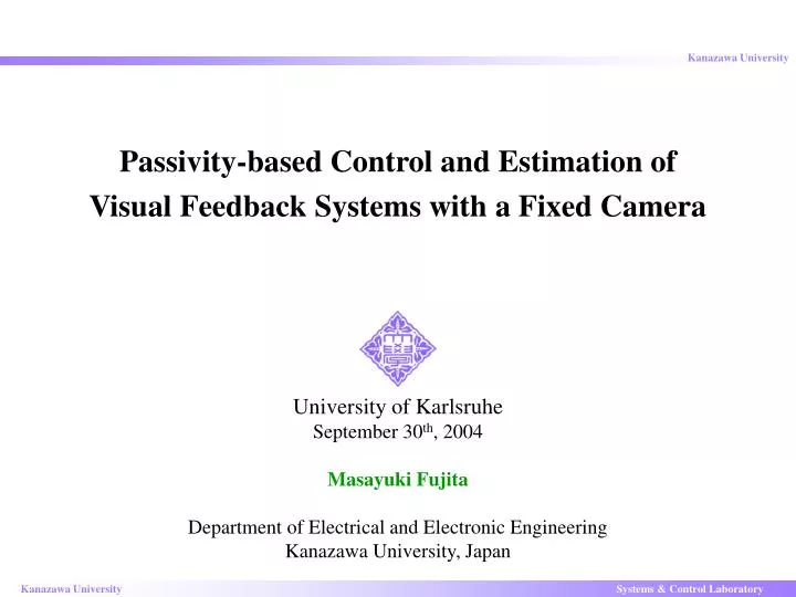
Passivity-based Control and Estimation of Visual Feedback Systems with a Fixed Camera. University of Karlsruhe September 30 th , 2004 Masayuki Fujita Department of Electrical and Electronic Engineering Kanazawa University, Japan. Introduction. Image. Camera. Robot. World Frame.

E N D
Passivity-based Control and Estimation ofVisual Feedback Systems with a Fixed Camera University of Karlsruhe September 30th, 2004 Masayuki Fujita Department of Electrical and Electronic Engineering Kanazawa University, Japan
Introduction Image Camera Robot World Frame Target Object Application of Visual Feedback System • Fixed-camera Configuration Camera • Swing Automation for Dragline • Autonomous Injection of Biological Cells etc. Robot Image • Eye-in-Hand Configuration • Automatic Laparoscope (Surgical Robot) etc. World Frame Target Object Fig. 1(a): Fixed-camera Fig. 1(a): Eye-in-Hand In the previous work, almost all the proposed methods depend on the camera configuration. One of methods for the eye-in-hand configuration has been discussed in ACC, 2003. In this research, it will be extended to the fixed-camera configuration. Our proposed methods have the same strategy for both camera configurations. Fig. 2: Some Examples of Visual Feedback System
Objective of Visual Feedback Control Rodrigues’ formula Direction of Rotation: Angle of Rotation: Known Information Composition Rule Unknown Information ( Target motion is unknown.) Position and Orientation Homogeneous Representation Fig. 3: Visual Feedback System Objective of Visual Feedback Control One of the control objective is to track the target object in the 3D workspace. The relative rigid body motion must tend to the desired one
Fundamental Representation Fig. 3: Visual Feedback System is the difference between and . ( Camera is static. ) Fundamental Representation of Relative Rigid Body Motion (1) Body Velocity of Camera Body Velocity of Target Object : Translation : Orientation not measurable Relative Rigid Body Motion in Fixed Camera Configuration : OMFC OMFC (Object Motion from Camera) (2) Fig. 4: Block Diagram of OMFC
Camera Model and Image Information Camera Frame Image Plane : Focal Length World Frame ( depends on .) not measurable measurable OMFC Camera Relative Feature Points (3) Perspective Projection (4) Target Object Fig. 5: Pinhole Camera Image Information (m points) (5) Fig. 6: Block Diagram of OMFC with Camera Image information fincludes the relative rigid body motion .
Nonlinear Observer in VFS Fig. 3: Visual Feedback System Camera Model EsOMFC Estimated OMFC Estimated Body Velocity (6) (2) estimated Model of Estimated Relative Rigid Body Motion:EsOMFC : Input for Estimation Error Estimated Image Information (7) (8) Fig. 7: Block Diagram of Estimated OMFC
Nonlinear Observer in VFS continued not measurable measurable OMFC Camera + Estimation Error System Camera Model EsOMFC (10) estimated estimated Estimation Error (Error between Estimated State and Actual One) estimated (Vector Form) Fig. 3: Visual Feedback System Relation between Estimation Error and Image Information (9) Fig. 8: Block Diagram of OMFC and Estimated OMFC
Control Error System Control Error System HMFC (12) + (This is dual to the estimation error system.) Desired RRBM Control Error (Error between Estimated State and Desired One) Fig. 3: Visual Feedback System (Vector Form) Estimated Information Relative Rigid Body Motion from to by Composition Rule (HMFC: Hand Motion from Camera) (11) Fig. 9: Block Diagram of HMFC and Reference
Visual Feedback System Estimation Error System OMFC Camera + Camera Model EsOMFC + Control Error System HMFC Visual Feedback System with Fixed Camera Configuration (13) Fig. 10: Block Diagram of Control and Estimation Error Systems
Visual Feedback System OMFC Camera + + Camera Model EsOMFC + Controller HMFC Visual Feedback System with Fixed Camera Configuration (13) Fig. 11: Block Diagram of Visual Feedback System
Property of Visual Feedback System Lemma 1 If the target is static , then the visual feedback system (13) satisfies (14) where is a positive scalar. OMFC Camera + + Camera Model EsOMFC + HMFC Controller Fig. 11: Block Diagram of Visual Feedback System
Property of Visual Feedback System continued Energy Function (15) Error Function of Rotation Matrix (Proof) Differentiating the energy function (15) with respect to time along the trajectories of the visual feedback system yields skew-symmetric matrices Integrating both sides from 0 to T, we can obtain (Q.E.D.) (14) Passivity Property of Manipulator Dynamics is a skew-symmetric matrix
Stability Analysis Passivity-based Visual Feedback Control Law Gain (16) If , then the equilibrium point for the closed -loop system (14) and (16) is asymptotically stable. Theorem 1 OMFC Camera + + Camera Model EsOMFC + HMFC Controller Fig. 11: Block Diagram of Visual Feedback System
L2-gain Performance Analysis Tracking Problem Based on the dissipative systems theory, we consider L2-gain performance analysis in one of the typical problems in the visual feedback system. Disturbance Attenuation Problem OMFC Camera + Camera Model EsOMFC + + HMFC Fig. 12: Generalized Plant of Visual Feedback System
L2-gain Performance Analysis Tracking Problem Based on the dissipative systems theory, we consider L2-gain performance analysis in one of the typical problems in the visual feedback system. Disturbance Attenuation Problem Given a positive scalar and consider the control input (31) with the gains and such that the matrix P is positive semi-definite, then the closed-loop system (28) and (31) has L2-gain . Theorem 2 • represents a disturbance attenuation level of the visual feedback system. • Other problems can be considered by constructing the adequate generalized plant.
Conclusions ( is the difference between and .) Visual Feedback System • Fundamental Representation of • Relative Rigid Body Motion Fig. 3: Visual Feedback System • Nonlinear Observer in Visual Feedback System • Passivity of Visual Feedback System Energy Function • Stability Analysis Lyapunov Function • L2-gain Performance Analysis Storage Function Our proposed methods have the same strategy for both camera configurations. Future Works • Dynamic Visual Feedback Control (with manipulator dynamics) • Uncertainty of the camera coordinate frame (one of calibration problems)
Appendix Appendix
Introduction Control Vision Robotics Application of Visual Feedback System • Swing Automation for Dragline • Autonomous Injection of Biological Cells • Automatic Laparoscope (Surgical Robot) etc. Research Field of Visual Feedback System Fig. 1: Some Examples of Visual Feedback System Visual Feedback Control (Machines + Visual Information) x Control Control will be more important for intelligent machines as future applications. In this research Fig. 2: Research Field of VFS • Visual Feedback Control with Fixed-camera • Passivity-based Control
Outline 1. Introduction 2. Objective of VFC and Fundamental Representation 3. Nonlinear Observer and Estimation Error System 4. Control Error System 5. Passivity-based Control of Visual Feedback System 6. Conclusions
Homogeneous Representation Rodrigues’ formula Direction of Rotation: Angle of Rotation: Position and Orientation Homogeneous Representation Fig. a1: Visual Feedback System Relative Rigid Motion Camera Motion (a1) Target Object Motion Relative Rigid Motion
Fundamental Representation of Relative Rigid Body Motion Body Velocity by Homo. Rep. Body Velocity : Translation (a3) (a2) : Orientation (Ref.: R. Murray et al., A Mathematical Introduction to Robotic Manipulation,1994.) Body Velocity of Camera Motion Body Velocity of Target Object Motion (a4) (a5) Body Velocity of Relative Rigid Body Motion by Homo. Rep.
Fundamental Representation of Relative Rigid Body Motion continued Body Velocity of Relative Rigid Body Motion (a6) (by Homo. Rep.) (1) (by Adjoint Transformation) (Fundamental Representation of Relative Rigid Body Motion:RRBM) (a7) (Adjoint Transformation) (Ref.: R. Murray et al., A Mathematical Introduction to Robotic Manipulation,1994.) RRBM Fig. a2: Block Diagram of RRBM
Estimation Error System Estimation Error System (10) (a8) (This system is obtained from (a8) by the property of Adjoint Transformation (a7).) ( Detail of Derivation of Estimation Error System )
Image Jacobian Relation between Estimation Error and Image Information (9) Taylor Expansion with First Order Approximation
Image Jacobian continued Representation by 4 dimension Representation by 3 dimension
Image Jacobian continued Relation between Estimation Error and Image Information (9)
Camera Frame World Frame Hand Frame Object Frame Experimental Testbed on a 2DOF Manipulator Fig. 13: Experimental Testbed for Dynamic Visual Feedback Control
Fig. 15: Trajectory of Manipulator Experiment for Stability Analysis Field of View Target Object 2DOF Manipulator Fig. 14: Initial Condition Gains
Experimental Results (Stability Analysis) Experimental Results Fig.16: Control Errors Fig. 17: Estimation Errors Fig. 19: Euclid Norm of States Fig. 18: Joint Velocity Errors
L2-gain Performance Analysis in Experiment Target Motion in Experiment The target moves on the xy plane for 9.6 seconds. Fig.20(b): Figure 8 Motion Fig. 20(a): Straight Motion
Gain A Gain B Experimental Results for L2-gain Performance Analysis Experimental Results Gain A Gain B represents a disturbance attenuation level. Fig. 21: Norm of z