Download

1 / 19
190 likes | 336 Views
ISIS Upgrade Options. ISIS Accelerator Division. John Thomason. 0.24 MW ISIS. • Assumes an optimised 2RF system giving 300 µA in the synchrotron • 4/5 pulse pairs to TS-1 (192 kW) and 1/5 pulse pairs to TS-2 (48 kW) • Must keep beam to TS-2 for the foreseeable future.

E N D
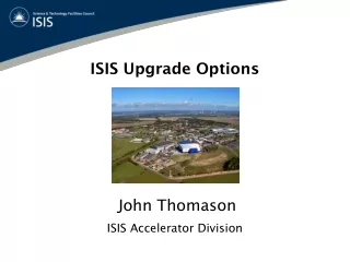
ISIS Upgrade Options ISIS Accelerator Division John Thomason
0.24 MW ISIS • Assumes an optimised 2RF system giving 300 µA in the synchrotron • 4/5 pulse pairs to TS-1 (192 kW) and 1/5 pulse pairs to TS-2 (48 kW) • Must keep beam to TS-2 for the foreseeable future
Upgrade Options •Upgrade routes for ISIS are summarised in the table above. All designs are to be developed primarily for an optimised neutron facility, and should provide provision of an appropriate proton beam to the newly built TS-2. The list here is not exhaustive, but presents the main, reasonable routes that would provide a major boost in beam power. Primary considerations are the cost relative to a new facility and the impact on ISIS operations.
• Replaces oldest and probably most vulnerable part of ISIS accelerators • Increased energy (up to 180 MeV) gives increased intensity in synchrotron and more beam to target • Similar designs are already available e.g. CERN Linac4, J-PARC • Would require a new building and reconfiguration of the TS-1 neutron and muon targets Linac Upgrade
(Steve Jago, Stuart Birch, Adrian McFarland) 180 MeV Injection • HEDS Line • - DC Dipoles and • Quadrupoles • Vertical “Sweeper” • - Pulsed Dipole • Injection Septum • - High Current DC Dipole • Injection Dipoles • - 4 Pulsed Dipoles • - Closed Orbit Bump • Stripping Foil - Beam rigidity - Aperture - Beam rigidity - Increased field/current/voltage - Stripping efficiency - Lifetime • Single Turn / Ferrite Core • 155 mm Aperture • Peak Field ~ 0.11 T for 70 MeV • Peak Current ~ 12200 A • Rise / Fall Time ~ 80 µs • Flat-top ~ 400 µs
70 MeV Magnetic Model • Calculated current - 12195 A • Actual current – 12200 A • Calculated voltage - 175 V • Actual voltage ~ 250 – 300 V
180 MeV Magnetic Model • Peak field ~ 0.18 T for 180 MeV • Calculated current - 20725 A • Calculated voltage - 290 V
Power Supply • I > 21000 A • Rise/fall ~ 80 µs • Flat-top ~ 400 µs • Possibility of tuneable • gradient on “flat-top” Current waveform Voltage waveform
(Chris Prior) 180 - 800 MeV Acceleration • Initial calculations (done in 2003) show that 180 MeV injected • beam should be cleanly accelerated to 800 MeV in the ISIS ring at • intensity levels giving 0.5 MW on target • There should already be enough RF acceleration available in the • ISIS ring to accommodate this (calculations were better • optimised for fundamental only rather than dual harmonic • acceleration) • Did not include transverse effects • Requires beam chopping
Recommended MW Upgrades • Based on a ~ 3 GeV RCS fed by bucket-to-bucket transfer from ISIS 800 MeV synchrotron (1MW) • RCS design also accommodates multi-turn charge exchange injection to facilitate a further upgrade path where the RCS is fed directly from a 800 MeV linac (2 – 5 MW)
(Chris Warsop, Grahame Rees, Dean Adams, Ben Pine, Bryan Jones, Rob Williamson) RCS Rings
Outline Work Plan • Main topics to cover • Longitudinal Calculations/Simulations for candidate FI Rings, then MTI • Build up MTI simulation 2Dto 3D, then acceleration • Model Injection Magnet and Region (CST based, as profile monitors) • Transverse Space Charge and Working Point, Correction Schemes • Lattice Optimisation, Analysis, Correction • Instabilities: standard checks, e-p work • Collimation: outline designs, full simulations with activation • Review all main systems Pull work together: comparisons • Best lattice and ring size; RF and MMPS combinations • Estimated losses and activation Started Next Uncertain Cover
Simulation Hardware • SCARF: • Linux only: Red Hat Enterprise 4.4 • GNU, Intel, PGI compilers for Fortran, C, java • AMD, Intel, ATLAS, Goto BLAS, BLACS, • ScaLAPACK, FFTW libraries • MPI is the parallel framework • 3 main sections of cluster • Can choose section or just submit • Access by grid certificate • Obtained from e-Science locally • ORBIT MPI installed as a module • Synchrotron Physics and Intense Beams Groups have purchased 17 nodes • = 136 processors • Will be available soon after 16th February • Larger jobs possible using normal SCARF queues • Will still maintain access to 16 processor development rig
Simulation Codes • ORBIT MPI: • Strip-foil injection, including • painting and foil scattering • RF focusing and acceleration • Transport through various • magnetic elements • Longitudinal and transverse • impedances • Longitudinal, transverse, and • three-dimensional space charge • forces • Collimation and limiting apertures • Calculation of many useful • diagnostic quantities • Parallel version of ORBIT available • on SCARF • Set Development (Ben Pine): • Parallel version of Set running • on SCARF • Currently 2D with space charge • Work advancing on adding • 2.5D • Main goals this year: • - Benchmarking against • standards • - Adding new 2D boundary • conditions • - Starting to think about full • 3D • And: • Add other software • Add other accelerator codes
Visualization • e-Science Application Development Group • Parallel visualization cluster • Expertise in data mining, computational steering • Could use existing tools if data put into nexus data format • http://www.nexusformat.org/Main_Page Simulation hardware, code and visualization resources on site to do the world-class accelerator physics required for ISIS upgrades
(Grahame Rees, Ciprian Plostinar) 800 MeV H- Linac • Design Parameters: • Beam power for 2 MW, 30 Hz, 3.2 GeV RCS: 0.5 MW • Beam pulse current before MEBT chopping: 43.0 mA • Beam pulse current after MEBT chopping: 30.0 mA • Number of injected turns for 370 m RCS: ~500 turns • Beam pulse duration at the 30 Hz rep rate; ~700.0 μs • Duty cycle for the extent of the beam pulse; ~2.1 % • MEBT(in) normalised rms emittances: 0.25, 0.375 (π) mm mr • MEBT(out) normalised rms emittances: 0.292, 0.42 (π) mm mr • Cell equipartition transv/long phase shift ratios: 1.40
All options have the same 324 MHz, 74.8 MeV stage 1: Design Options RFQ MEBT DTL IEBT 74.8 MeV Options F (MHz) Stage 2 Stage 3 Stage 4 1 648 ScL 1 ScL 2 ScL 3 2 648 CCL ScL 2 ScL 3 3 972 ScL d ScL e ScL c 4 324-?-972 ScL a ScL b ScL c ~200 MeV 800 MeV
Beam Envelopes forOption 2 DTL CCL (193 MeV) ScL (800 MeV)
800 MeV H- LinacStudies Still Needed MEBT comparisons Selection of option ScLa/b spoke cavities? Refine stage matchings Linac error effect study Effect of failed cavities Ring collimation line