Download
1 / 39
390 likes | 532 Views
A telematic tool for computer aided lumbar spine surgery planning. CRAFT-1999-71634 / IST-1999-57. Context and Introduction. GEOMETRY. APPLY CONSTRAINTS. MATERIAL PROPERTIES. MODEL : VIRTUAL ANALOGUE. PREDICT RESPONSE. Background. ISO 17025. Numerical simulation. In vitro experiments.

E N D
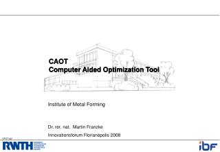
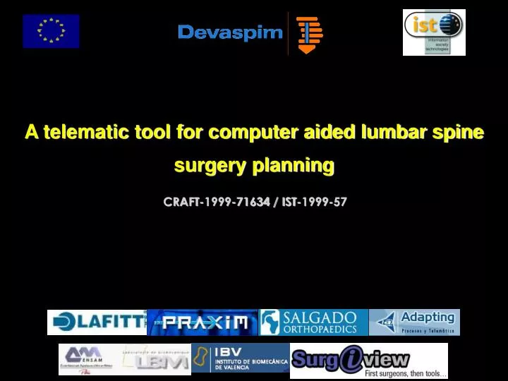
A telematic tool for computer aided lumbar spine surgery planning CRAFT-1999-71634 / IST-1999-57
GEOMETRY APPLY CONSTRAINTS MATERIAL PROPERTIES MODEL : VIRTUAL ANALOGUE PREDICT RESPONSE
Background ISO 17025 Numerical simulation In vitro experiments complementary
fixation compensatory motion OP OP OP Lumbar Spine surgery WHAT IS THE BEST STRATEGY FOR A GIVEN PATIENT? Long term disc degenerescence (Guigui 98, Schlegel 96, ...).
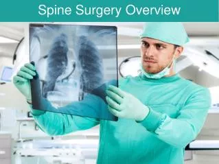
Some biomechanical Finite Element Method (FEM) models exist but not accessible to non-FEM experts such as: surgeons, implant designers and implant manufacturers. Devaspim = a tool accessible via internet, to calculate the biomechanical behaviour of the instrumented spine using the FEM and to aid for surgery planning
This tool will help to minimise the number of implant failures : - Optimise design process of lumbar spine implants • by reducing failure due to implant design and improving competitiveness of the manufacturers (implant industries) in the segment of spine implants. • - Minimise technical failures • due to the selection of inappropriate configurations, through a better preoperative planning. The application use will be a service offered to surgeons/designers by the implant manufacturers
DESCRIPTION USER RESULT INPUT WEB PAGE (Spain) spine surgery data: - patient general data - pathology data User User friendly friendly - surgical method Interface Interface input output - implant configurations Output Output parameters parameters Storage in a transmission transmission data base Devaspim CALCULATION SERVER (France) Interface Instrumented Interface input output spine FEM model Biomechanical behaviour of instrumented spine
STEP1 : Morphology Manually Introducing the X-Rays Spine Morphology
STEP1 : Morphology 3D shape and position
STEP1 : Morphology Personalised FEM Generic FEM 3D Reconstruction
STEP1 : Morphology Example : degenerative L4/L5 Spondylolisthesis
STEP 2 : General Data • Bone quality • Imbalance • Weight • Height
STEP 2 : General Data FEM : Personalized bone mechanical Properties (osteoporosis) FEM : Personalized calculations of Loads to apply on the model • Bone quality • Imbalance • Weight • Height
Pathology type: • Spondyloarthrose • Spondylolisthesis • Fractures • Affected level • Restoration estimation STEP 3 : Pathology definition
STEP 3 : Pathology definition • Pathology type: • Spondyloarthrose • Spondylolisthesis • Fractures • Affected level • Restoration estimation
STEP 3 : Pathology definition • Pathology type: • Spondyloarthrose • Spondylolisthesis • Fractures • Affected level • Restoration estimation
STEP 3 : Pathology definition IT IS POSSIBLE TO MODEL AUTOMATIQUELY A WIDE RANGE OF LESIONS Disc Disease Modification of components Osteoporosis Modification of the bone’s Young Modulus
STEP 4 : Kind of instrumentation Choose the implant system to simulate
STEP 4 : Kind of instrumentation Choose the implant system to simulate
STEP 5 : Implant Configuration • Characteristics to define for the implant system chosen • Material • Symmetric or not • Screw diameter by level • Screw length by level • Connectors by level • Rod diameter
STEP 5 : Implant Configuration • Parameterization : • Material • Connector • For each instrumented vertebra, kind of connector to model
STEP 5 : Implant Configuration • Parameterization : • Material • Connector • For each instrumented vertebra, kind of connector to model • Screw • For each instrumented vertebra, diameter, length, angle of insertion
STEP 5 : Implant Configuration • Parameterization : • Material • Connector • For each instrumented vertebra, kind of connector to model • Screw • For each instrumented vertebra, diameter, length, angle of insertion • Rod diameter • Hooks • DTT Kind, number and localization
STEP 6 : Surgical technique (optional) A surgical gesture is associated to the implant chosen
Discectomy Facectomy Laminectomy Arthrectomy STEP 6 : Surgical technique (optional) A surgical gesture is associated to the implant chosen …
STEP 7 : Results SPECIFIC IMPLANTS RESULTS • Assembly stiffness • Rods stress • Screw stress • Biomechanical behaviour of the assembly
STEP 7 : Results The simulation outputs An html report automatically generated will be send to the user : Result.html
STEP 7 : Results Analysis of the anatomical entities : • Stress in the adjacent intervertebral disc • Facets loads • …
STEP 7 : Results Shear load Low, medium, high Bending moment Low, medium, high Pull out load Low, medium, high Bone implants stresses Qualitative estimation of configuration
3D Reconstruction Finite Element Model Calculation. Example L4 L5 Degenerative Spondylo L4 L5 instrumenation
Flexion STRESSES IN LOWER SCREWS Calculation. Example
Lumbar Spine surgery PATIENT SURGICAL ACT Devaspim IMPLANT
CONCLUSION Computer aided surgery planning: innovative tool For Surgeons: • understand mechanical effects of a given strategy • minimise implant failures • Better clinical outcome • For implant designers • implant design improvements • implant effects in expected indications
CONCLUSION DEVASPIM SPIN-OFF - Implant manufacturers: decreased design costs - Orthopaedic surgeons: better preoperative planning - Patients: increased clinical outcome and quality of life - Health Services: cost reduction due to less re-operations.