Download
1 / 12
120 likes | 261 Views
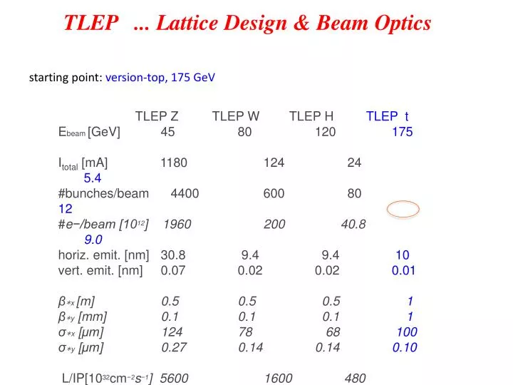
TLEP . .. Lattice D esign & Beam Optics. starting point: version-top, 175 GeV. TLEP Z TLEP W TLEP H TLEP t E beam [ GeV ] 45 80 120 175 I total [ mA ] 1180 124 24 5.4 #bunches/ beam 4400 600 80 12

E N D
TLEP ... Lattice Design & Beam Optics starting point: version-top, 175 GeV TLEP Z TLEP W TLEP HTLEP t Ebeam[GeV] 45 80 120 175 Itotal[mA] 1180 124 24 5.4 #bunches/beam 4400 600 80 12 #e−/beam [1012] 1960 200 40.8 9.0 horiz. emit. [nm] 30.8 9.4 9.4 10 vert. emit. [nm] 0.07 0.02 0.02 0.01 β∗x[m] 0.5 0.5 0.5 1 β∗y[mm] 0.1 0.1 0.1 1 σ∗x [μm] 124 78 68 100 σ∗y [μm] 0.27 0.14 0.14 0.10 L/IP[1032cm−2s−1] 5600 1600 480 130
TLEP ... Lattice Design not the very first steps anymore (... V8.c) Text-Book like approach still 80 km, standard FoDo structure fill factor, robustness, easy to handle & modify easy to understand & optimise analytically Choice of single cell: compared to V.3 ...V.6 cell length increased to Lcell = 50m equilibrium emittance scaling of dispersion in a FoDo
TLEP ... single cell Lcell=50m Dipole: Ndipole = 2784 Ldipole = 21.3 m due to techn. reasons: 2 * 11 m bending angle = 2.2 mrad B0 = 610 Γ Quadrupole: Lquadrupole= 1.5 m k=3.55*10-2 m-2 g=20.7 T/m β ≈ 100m, Dx= 15.3 cm
TLEP ... Lattice Design 24 Arcs :56 standard FoDo cells & 2 half bend cellsat beginning and end length of arc: 3.0km each arc is embedded in dispersion free regions ... arcs are connected by straight sections ... 12 long (mini β and RF) ... 12 ultra shortiestbc to be optimised
TLEP Straights 8 Straights :9 empty (i.e. dispersion free) FoDocellsincluding matching sections arc-straight, l = 450m arc cells empty cells arc cells empty cells to be optimised: βy at matching section, needs an additional quadrupole lens already built in but not used yet. and / or optimisation of the lens positions
TLEP Octant Straight – Arc – Arc - Straight
TLEP Mini-Betas 4 Mini-beta-Insertions :based on empty (i.e. dispersion free) FoDo cells L*=4m β*x =1m, β*y =1mm standard doublet structure & matching section βm,ax=18 km
TLEP The Ring Lring = 76.3km 4 min- betas, 24 disp free straights, 12 long straights 8 for rf equipment, 4 for mini-betas * * * * * * * * * * * *
TLEP ... Lattice Design V8.c The Ring: a kind of three times LEP Main Parameters: momentum compaction energy loss per turn: MADX: αcp=8.6*10-6 MADX: ΔU0=8.64 GeV
TLEP ... V 8.c Main Parameters: Damping & Beam Emittance
Synchrotron Radiation Power Np= 9*1012 ΔU0 = 8.64 MeV T0 = 263 μs ... and Saw-Tooth effect rf distributed over 12 straights and 216 cavities (60MV each)
Next steps: * Optics fine tuning * Do we really need Dx= 15 cm or should we relax ?? * Establish complete versions for different Mini Beta Options * Optimise RF distribution how many straights do we really need ??? * 80 km / 100 km ??? tbd * start with the Ph.D. topics: what about the momentum acceptance ???