Download
1 / 1
10 likes | 229 Views
Goddard Space Flight Center. OPTIMIZED HEAT INTERCEPTION FOR CRYOGEN TANK SUPPORT. HEAT EXCHANGER DESIGN FOR SMALL TO LARGE SCALE LOX-LH2 CRYOGENIC PROPELLANT STORAGE TANKS Justin McCabe Mentor: Dr. Ed Canavan AETD/Code 552 - Cryogenics and Fluids Branch NASA – Goddard Space Flight Center.

E N D
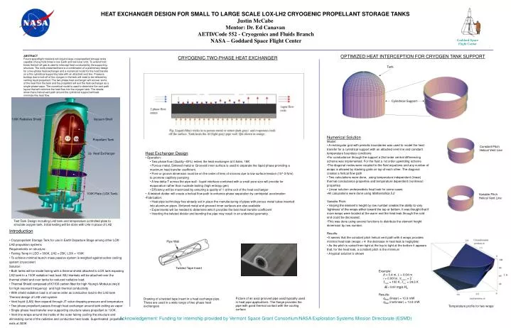
Goddard Space Flight Center OPTIMIZED HEAT INTERCEPTION FOR CRYOGEN TANK SUPPORT HEAT EXCHANGER DESIGN FOR SMALL TO LARGE SCALE LOX-LH2 CRYOGENIC PROPELLANT STORAGE TANKSJustin McCabeMentor: Dr. Ed Canavan AETD/Code 552 - Cryogenics and Fluids Branch NASA – Goddard Space Flight Center ABSTRACT Future spaceflight missions will require large cryopropellant storage tanks capable of long hold times in low Earth and low lunar orbit. To extend hold times the boil-off gas is used to intercept heat conducted by the supporting structure. The work presented here is a combination of a preliminary design for a two-phase heat exchanger and a numerical model for the heat transfer on a thin cylindrical supporting tube with an attached vent line. Pressure buildup due to boil-off of the cryogen in the tank will need to be relieved by venting liquid propellant. The two-phase heat exchanger will recover some of the heat from the tank and the propellant will exit the heat exchanger as a single-phase vapor. The numerical model is used to determine the vent path layout that will minimize the heat flow into the cryogen tank. The results show that a helical vent path around the cylindrical support will best minimize this heat flow. CRYOGENIC TWO-PHASE HEAT EXCHANGER Tank Cylindrical Support 100K Radiative Shield Vacuum Shell • Numerical Solution • Model: • A rectangular grid with periodic boundaries was used to model the heat transfer for a cylindrical support with an attached vent line and constant temperature boundary conditions • For conductance through the support a 2nd order central differencing scheme was implemented. For the fluid a 1st order upwinding scheme • The diagonal nodes were coupled to the fluid equations and any number of wraps is allowed by stacking grids on top of each other. The diagonal creates a helical flow path • Two calculations were done, using temperature independent (linear) thermal conductance properties and temperature dependent (nonlinear) properties • Linear solution underpredicts heat leak for some cases • All calculations were done using Mathematica 5.2 • Variable Pitch: • Varying the element’s height by row number creates the ability to vary ‘tightness’ of the wraps either toward the top or bottom. It was thought that if more wraps were located at the warm end the heat leak through the cold end could be decreased. • This was done using several functions to distribute the element height dimension by row number. • Results: • It seems that the constant pitch helical vent path with 4 wraps provides minimal heat leak (wraps > 4 the decrease in heat leak is negligible) • As the pitch is varied from tight at the top to tight at the bottom it appears that, for the heat leak, a constant pitch is the minimum • A typical solution is shown Propellant Tank Constant Pitch Helical Vent Line • Heat Exchanger Design • Operation: • Two phase flow (Quality~45%) enters the heat exchanger at 0.5atm, 18K • Porous metal, Sintered metal or Grooved inner surface is used to separate the liquid phase providing a maximum heat transfer coefficient. • Pore or groove dimension must be on the order of tens of microns due to low surface tension (10^-3 N/m) to promote capillary pumping • A low delta-T across the pipe wall - liquid interface combined with a small pore size will provide for evaporation rather than nucleate boiling (high entropy gen) • Efficiency will be maximized by ensuring a quality of 1 at the exit of the heat exchanger • A twisted divider will create a helical flow path to enhance phase separation by centripetal acceleration • Fabrication: • Heat pipe technology has already set in place the manufacturing of pipes with porous metal tubes inserted into aluminum pipes. Sintered metal and grooved inner surfaces are also available • Experiments will be needed to determine which provides the best heat transfer coefficient • Inserting the twisted divider and bending the pipe may result in an undesired geometry. 2 Heat Exchanger 100K Plate (LOX Tank) Variable Pitch Helical Vent Line Test Tank Design including LH2 tank and temperature controlled plate to simulate oxygen tank. Initial testing will be done with LHe in place of LH2 • Introduction • Cryopropellant Storage Tank for use in Earth Departure Stage among other LOX-LH2 propulsion systems • Requirements on structure: • Fairing Temp in LEO = 300K, LH2 = 25K, LOX = 100K • To achieve minimal launch mass passive system is weighed against active cooling system (cryocooler) • Solution: • Both tanks will be inside fairing with a thermal shield attached to LOX tank exposing LH2 tank to a 100K radiation heat load. MLI blankets will be attached over the thermal shield and over tanks for reduced radiative load. • Thermal Shield composed of K1100 carbon fiber for high Young’s Modulus (req’d for high resonant frequency) and high thermal conductivity • With shield radiation load is of same order as conductive load to the LH2 tank • Thermal design of LH2 vent system: • Vent liquid (LAS) then expand through JT valve dropping pressure and temperature • Two phase propellant passes through heat exchanger around tank exiting as vapor • Single phase heat transfer over supporting structure raises propellant to 100K. • Vent line wraps around the inside of the outer fairing cooling the structure and eliminating some of the radiative and conductive heat loads. Superheated propellant exits at 300K Pipe Wall Twisted Tape Insert • Example: • R = 0.4 m, L = 0.64 m • t = 0.001m, Nwraps = 2 • Thigh = 100 K, Tlow = 24.6 K • Results: • qleak (linear) = 10.9 mW • qleak (nonlinear) = 13.8 mW Picture of an axial grooved pipe used typically used in heat pipe applications. The flange provides the pipe with good thermal contact with the cooling surface Drawing of a twisted tape insert in a heat exchange pipe. These are used in a wide range of two phase heat exchangers Temperature profile for two wraps Acknowledgement: Funding for internship provided by Vermont Space Grant Consortium/NASA Exploration Systems Mission Directorate (ESMD)