Download
1 / 48
480 likes | 587 Views
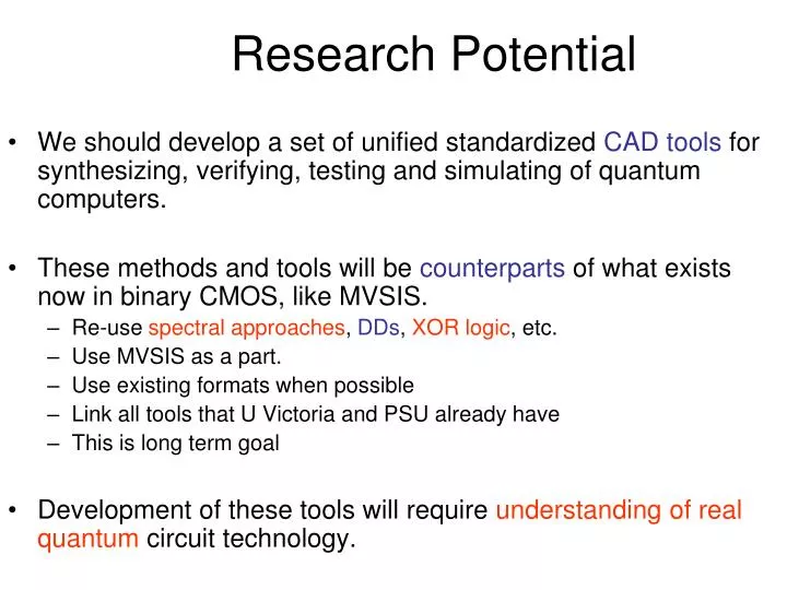
Research Potential. We should develop a set of unified standardized CAD tools for synthesizing, verifying, testing and simulating of quantum computers. These methods and tools will be counterparts of what exists now in binary CMOS, like MVSIS.

E N D
Research Potential • We should develop a set of unified standardized CAD tools for synthesizing, verifying, testing and simulating of quantum computers. • These methods and tools will be counterparts of what exists now in binary CMOS, like MVSIS. • Re-use spectral approaches, DDs, XOR logic, etc. • Use MVSIS as a part. • Use existing formats when possible • Link all tools that U Victoria and PSU already have • This is long term goal • Development of these tools will require understanding of real quantum circuit technology.
New Frontiers Quantum Computer My statements below may be provocative and I may be wrong. But I am curious what you think.
Open Problems in Quantum Circuits • Synthesisof binary quantum cascades with no garbage or small garbage • (Maslov, Dueck, Miller, Kerntopf, Perkowski, Khlopotine, Mishchenko, Curtis, Khan, Jha and Agrawal, Hayes, Markov) • Synthesis of multiple-valued quantum cascades • (Muthukrishnan and Stroud, Miller et al, Khan, Perkowski, Curtis, Lee, Denler) • Universal gates, what are the counterparts of Toffoli and Fredkin gates? Fredkin Multiple-valued logic for CMOS makes no sense. MV for quantum is reasonable and has in long term better potential than binary Toffoli
Open Problems in Quantum Circuits • What is theFault Modelfor quantum circuits? • Technology dependent? People disagree • Formal Verificationof quantum circuits • Test Generationfor quantum circuits • Fault Localizationof quantum circuits • Synthesis of testablequantum circuits • Synthesis of fault-tolerant, error correcting quantum circuits. • Classification and matching
Open Problems in Quantum Circuits • What areuniversal gates? • What are best components of universal gates (CV?) • How to calculate costs of elementary gates for each quantum technology such as NMR or ion trap? • What are the gates that can be truly realizedin a quantum technology? Unlike n-input Toffoli • What are the synthesis, analysis and test methods for sequential quantum circuits?
Open Problems in Quantum Circuits • Invent new quantum algorithms. • What are the principles to create quantum algorithms • The nature ofentanglement. • Quantum computerarchitectures. • Quantumformalisms. (Clifford algebras). • Quantum Logic.
What size of (binary) Quantum Computers can be build in year 2002? • 7 bits
Is logic synthesis for quantum computers a practical research subject? Yes, it is a useful technique for physicists who are mapping logic operations to NMR computers. CAD for physicists. Isaac Chuang, IBM
Quantum Circuit Synthesis is not the same as reversible logic synthesis
Problem • We would like to assume that any two quantum wires can interact, but we are limited by the realization constraints • Structure of atomic bonds in the molecule determines neighborhoods in the circuit. • This is similar to restricted routing in FPGA layout - link between logic and layout synthesis known from CMOS design now appears in quantum. • Below we are interested only in the so-called “permutation circuits” - their unitary quantum matrices are permutation matrices
A B C D B D A schematics with two binary Toffoli gates Quantum wires A and C are not neighbors A C * * A * B * C D This is a result of our ESOP minimizer program, but this is not realizable in NMR for the above molecule, because there is no connection between A and C, for instance, in the molecule.
A * B B A * * C D * D C But this costs me two swap gates So we have to modify the schematics as follows May be expensive
Design Issues • 1. Local mirroring • 2.Variable orderingversusgate ordering • 3. Return to zero and folding • 4. Realization of complex multiple-valued reversible gates (permutation gates) using directly 1-qubit and 2-qubit quantum primitives
Technique of local mirror can improve your ternary circuits, reduce the number of zeros in inputs. Here is the explanation for ternary logic “Return to Zero” and Folding
Molecule - Driven Layoutand Logic Synthesis A A B B C C D D Allowed gate neighborhood for 2 qubit gates
A better design of a large Toffoli Gate • The purpose of the last Q (3) gate is to reset the scratch bit back to its original value 0. • With one more gate we can obtain an implementation of Q (4) that works irrespective of the initial value of the scratch bit: We can eliminate the last gate if we don’t mind flipping value of the scratch bit
Solution • One solution to connection problem in quantum NMR computers is to take into account these gate realization layout constraints in the logic synthesis phase – do not synthesize from non-realizable gates. • Basic gate in quantum logic is a 2*2 (2-qubit gate). We have to build from such gates.
Also, an arbitrary two-qubit quantum gate (described by a unitary matrix) can be constructed from such gates. • These methods can be used to hierarchically synthesize larger circuits [55,59] and can be generalized to ternary (or in general multi-valued) logic (see Figure 4) for the realization of universal ternary permutative controlled gate. • Universal quantum gate is created when operations are single-qubit ternary rotations Figure 4: Conceptual ternary multiplexer op = Logical Operations: +0, +1, +2 represent Galois Addition of constants 0, 1, and 2, respectively 01, 02, 12 represent logical replacement i.e. a 01 operation will replace 0->1, 1->0, and 2->2
Observe that any single-qubit operation can be written in the box, and also that any single qubit operation can be inserted to the control and data lines. • The control can be from top (as in the Figure 3b) or from the bottom. • The composition of this kind of multiplexed operations allows to create arbitrary permutative gate of reversible logic [55,59]. • Also, an arbitrary two-qubit quantum gate (described by a unitary matrix) can be constructed from such gates. Figure 3. Smolin/DiVincenzo realization of Toffoli gate as a prototype of a regular controlled quantum structure: (a) standard notation, (b) notation used in this paper to emphasize the similarity
A P f 1 Q B Generalized Ternary Feynman Gate If f1 is reversible , gate is correct, what about non-reversible f1, please check if the gate is still reversible
P A B Q f 2 R C Generalized Ternary 3*3 Toffoli Gate Do the same exercise as in previous slide, this will help you get intuition in MV logic.
Generalized Ternary n*n Toffoli Gate A1 . . . Do the same exercise as in previous slide, this will help you get intuition in MV logic. A n-1 f n-1 An A n-1 f n-1 (A1, …, An-1 )
P A B Q f 2 R C 0 1 S D 0 1 Generalized Ternary 4*4 Fredkin Gate Rewrite this part to quantum ternary notation with Galois Logic
Generalized Ternary n*n Fredkin Gate Do the same exercise as in previous slide, this will help you get intuition in MV logic. . . A1 . . . . A n-2 A n-1 f ‘n-1 (A1, …., A n-1 ) + A n f n-1 (A1, …., A n-1 ) f n-1 f 2 A n-1 0 1 A n-1 f n-1 (A1, …., A n-1 ) + A n f ‘n-1 (A1, …., A n-1 ) A n 0 1
P Q R P Q + + * A B C A B Feynman (b) Toffoli P Q R + + 1 0 * * C A B Kerntopf Gate
Kerntopf Gate • The Kerntopf gate is described by equations: P = 1 @ A @ B @ C @ AB, Q = 1 @ AB @ B @ C @ BC, R = 1 @ A @ B @ AC. • When C=1 then P = A + B, Q = A * B, R = !B, so AND/OR gate is realized on outputs P and Q with C as the controlling input value. • When C = 0 then P = !A * ! B, Q = A + !B, R = A @ B. • 18 different cofactors!
0 1 1 0 1 1 1 0 1 0 Conservative circuit = the same number of ones in inputs and outputs X3 xor3 Variable Davio Majority X2 xor2 Shannon Examples of balanced functions = half of Kmap are ones
Generalized Ternary 4*4 Kerntopf Gate P A Do the same exercise as in previous slide, this will help you get intuition in MV logic. B Q f 2 R C 0 1 S D *
MV Quantum Design Structures and Approaches • 1. GFSOP • 2. Multiple-Valued Reed-Muller • 3. Canonical Forms over Galois Logic (equivalents of PPRM, FPRM, GRM, etc) • 4. Multiple-Valued Maitra Cascades and Wave Cascades. • 5. Other cascades of specific type of elements • 6. Cascades of general gates
Example 1: First method to realize MV quantum circuits MV Tensor Products • Analogous to binary quantum circuits. • As an example, consider two qutrits. • When the two qutrits are considered to represent a state, that state is the superposition of all possible combinations of the original qutrits, where: This approach to multi-valued quantum circuits requires measurements with more than two basis states. Also, new gates should be defined as well as the synthesis methods for these gates.
Quantum MV Superposition • The superposition property allows the qubit states to grow much faster in dimension than classical bits, and the qudits faster than qubits. • In a classical system, n bits represent distinct states, whereas n qubits correspond to a superposition of 2n states and n qutrits correspond to a superposition of 3n states. • Because in contemporary quantum technologies every qubit is costly, higher radices than 2 give an advantage of improved processing and storage power at the same realization cost. • This is a strong argument for realization of multi-valued logic in quantum circuits. • In addition to standard advantages of mv logic, quantum mv logic may be superior to binary one because of different nature of entanglement.
Example 2: Second Method to realize MV quantum circuits. Bloch Sphere • The normalization ||2 + ||2 = 1 admits the parametrization = cos(/2) e j , = sin(/2) e j. • | = e j(cos ( / 2) |0 + e j sin ( / 2) |1 ). • Since the global phase of |has no observable effect, we may write |= cos(/2) |0+ e jsin(/2) |1. • The angles and define a point on the surface of a unit sphere – the Bloch sphere, see Fig. 1. • The Bloch sphere provides an excellent tool to visualize the state vector of a qubit. • This is a binary Bloch sphere, but a multi-valued counterpart of it can be also created.
Second method to realize multi-valued logic using binary quantum computing (cont). • Figure shows the location of 6 points, that may correspond to values of some multi-valued algebras. • For binary logic we use |0 and |1. • For quaternary logic we use |0, |1, |0+|1, and |0-|1. • For 6-valued logic we may use additionally |0 + j |1 and |0 - j|1. • A rotation or a combination of rotations leads from one value to any other value.
Second Method to realize MV quantum circuits (cont). • Above we showed how multiple-valued logic can be encoded in binary quantum computing. • Quaternary logic requires two binary measurements (readings). • The first reading distinguishes states |0 and |1, and the second reading uses additional rotation gates to distinguish between states |0+|1, and |0-|1. • It can be shown that the logic with 2nvalues requires n readings.
Example 3: Quantum Circuit Simulation • Simulation of quantum circuits plays absolutely fundamental role in many areas of quantum physics and engineering. • Simulation is used to: • verify correctness of the design, • analyze its properties and • find some interesting aspects that cannot be found by “hand and pencil” methods. • Fault simulation • Evolutionary algorithms • Researchers routinely use quantum simulators to help them with inventions and verify their design guesses.
Fast simulation is extremely important • Matrix methods are slow. • Acceleration is attempted to be achieved by two fundamental methods: • (1) acceleration of standard operations by using special hardware emulators, parallel computers or processor networks, • (2) creating new advanced data structures to represent quantum data more efficiently using standard computers.
Example 4: Quantum Decision Diagrams • New data structures, such as QUIDDs [Viamontes, Markov, Hayes] allow for implicit parallelism when executing Kronecker multiplications on them. • QUIDDs are based on ADDs and MTBDDs, • so hopefully in future other decision diagrams may be used to represent quantum circuits. • It is also expected that basic software engines used successfully in classical CAD (such as for instance SAT or ATPG methods) may be used to deal with quantum circuits. • Also, the fast simulators based on new types of decision diagrams should be in future parallelized and possibly accelerated in FPGA-based boards. • Even before quantum computers will be available, their emulations on standard computers and ASIC/FPGA may prove useful to solve some practical problems.
Example 5: Testing and diagnosis of quantum circuits • Patel, Markov, and Hayes showed that reversible circuits are much better testable than irreversible circuits. • This is because every test covers half faults and every fault is covered by half tests. • The reversible circuits are then “transparent” to faults, making them well observable and controllable. • We showed that fault localization in reversible circuits is easier. • We presented preliminary results on testing binary quantum circuits and on fault localization of quantum circuits.
Regular structures, especially for symmetric functions Q R P Q R P 0 1 0 1 A 0 1 A B C B C A circuit from two multiplexers Its schematics This is a reversible gate, one of many Notation for Fredkin Gates
Lattice Structure for Binary Logic F = S 1,3 (A,B,C) A 0 1 B C 0 1 1 0 S0 S1 S2 S3
YZ X YZ - - - - 00 01 11 10 X - - - - 0 1 1 0 1 0 YZ 0 1 1 1 1 0 1 0 garbage g - - - - f X garbage garbage h gf Y garbage hfg fgh 1 Z garbage 1 0 1 0 YZ X X - - - - 0 1 1 1 garbage 0 1 i fg garbage 0 1 0 1
What to remember? • Synthesis problems in quantum circuits that are related to technology, such as NMR constraints. • Linear Nearest Neighbor model • Other research issues related to technology of quantum circuit realization • A better design of large Toffoli gates • Adding SWAP gates to circuits for LNNM model. • The concept of binary quantum multiplexer • Generalization of Feynman, Toffoli and other binary quantum gates to ternary and multiple-valued quantum gates. • Generalized Fredkin and Kerntopf gates. • How to recognize balanced functions in Kmaps. Why balanced functions are useful and important? • States of MV quantum logic on the Bloch Sphere. • Lattice structure from Multiplexers versus Lattice Structure from Fredkin gates – synthesis methods.