Download
1 / 24
240 likes | 303 Views
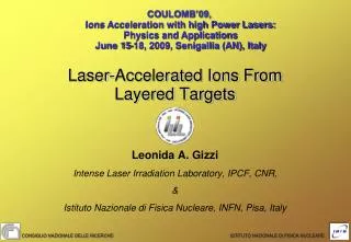
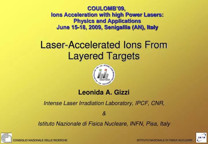
COULOMB’09, Ions Acceleration with high Power Lasers: Physics and Applications June 15-18, 2009, Senigallia (AN), Italy. Laser-Accelerated Ions From Layered Targets. Leonida A. Gizzi Intense Laser Irradiation Laboratory, IPCF, CNR, &

E N D
COULOMB’09, Ions Acceleration with high Power Lasers: Physics and Applications June 15-18, 2009, Senigallia (AN), Italy Laser-Accelerated Ions From Layered Targets Leonida A. Gizzi Intense Laser Irradiation Laboratory, IPCF, CNR, & Istituto Nazionale di Fisica Nucleare, INFN, Pisa, Italy CONSIGLIO NAZIONALE DELLE RICERCHE ISTITUTO NAZIONALE DI FISICA NUCLEARE
PEOPLE • Antonio GIULIETTI (CNR)* • Danilo GIULIETTI (Univ. Pisa, CNR)* • Leonida A. GIZZI (CNR)* • Luca LABATE (CNR)* • Moreno VASELLI (CNR-Associato)* • Walter BALDESCHI (CNR) • Antonella ROSSI (CNR) • Sergio BETTI (CNR)*, postdoc • Carlo A. CECCHETTI (CNR)*, PhD • Andrea GAMUCCI (CNR & Univ. of Pisa)*, PhD • Petra KOESTER (CNR & Univ. of Pisa)*, PhD • Tadzio LEVATO (CNR & Univ. of Pisa)*, PhD • Naveen PATHAK (UNIPI & CNR), PhD • Orlando CIRICOSTA (UNIPI and CNR), Tesi Laurea sp. • Francesco VITTORI (UNIPI and CNR), Tesi Laurea sp. • Francesco MICHIENZI (UNIPI and CNR), Tesi laurea tri. • * Also at INFN http://ilil.ipcf.cnr.it IL GRUPPO ILIL-CNR • CNR - DIPARTIMENTO MATERIALI E DISPOSITIVI • Progetto: Ottica, Fotonica e Plasmi • Unità (Commessa): FOTONICA DEGLI ALTI CAMPI • Fotonica degli alti campi per la generazione di impulsi ultracorti di radiazione X e particelle di alta energia; • Sviluppo di laser a larga banda per studi strategici sulla fusione per confinamento inerziale; CNR Research Campus, Pisa, Italy
COLLABORATION L.A. Gizzi, S. Betti, A. Giulietti, D. Giulietti, P. Koester, L. Labate, T. Levato* ILIL, IPCF-CNR and INFN, Pisa, Italy, * LNF-INFN, Frascati, Italy T. Kämpfer, I. Uschmann, E. Förster, IOQ, Univ. Jena, Germany F. Zamponi, A. Luebcke, Max Born Institute, Berlin, Germany A. P. L. Robinson Central Laser Facility, RAL, UK
The Fast Ignition scheme of Inertial Fusion Energy requires high current, fast electron beams to propagate efficiently in high solid density collisional plasmas; • Transient magnetic fields and neutralising plasma return current occur; • Knowledge is needed on the state of the material in which f.e. propagation occurs; • X-ray spectroscopy is the principal tool for accomplishing this task; • Return current will give rise to resistive thermal heating that will modify the spectral features of X-ray fluorescence; UNDERLYING MOTIVATION: FAST ELECTRON TRANSPORT Need to investigate PROPAGATION AND ENERGY DEPOSITION of fast electron beam inside the material
FAST ELECTRON PROPAGATION STUDIES Experiments performed also at the Jena (IOQ) laser facility within the LASERLAB access. WE USE LARGE AREA, MULTI-LAYER METALLIC and METAL-INSULATOR TARGETS Optical spectroscopy Ni 10µm Charged particle detector Laser 80 fs; up to 0.6 J ≈ 5x10¹⁹ W/cm2 Fe 10µm Cr 1.2µm “Rear” pin hole camera “Front” pin hole camera
X-RAY IMAGING OF FRONT AND REAR SIDE LASER Cr 1.2 µm 10µm Ni 10µm Fe 50 µm
FORWARD ESCAPING FAST ELECTRONS Target Radiochromic film layers Laser Spectrum is obtained matching dose released in each layer with predictions of MC (GEANT4) through an iterative process.
FORWARD ESCAPING FAST ELECTRONS Target Radiochromic film layers Laser Forward emitted charged Particles (electrons)
FORWARD ESCAPING FAST ELECTRONS Electron spectrum at E < 1MeV Cr+Ni+Fe target Fit with a “relativistic Maxwellian” Yields a fast electron temperature of 160 keV
ION ACCELERATION IN THE TNSA SHEATH Acceleration of the target ions driven by the fast electrons Fast Electrons Foil target L. Romagnani et al., Phys. Rev. Lett. 95 195001 (2005). S. Betti et al., Plasma Phys. Contr. Fusion 47, 521-529 (2005). F. Ceccherini et al., Laser Phys. 16, 594-599 (2006). J. Fuchs et al. Nature Physics 2, 48 (2006).
Towards High-Quality Ion Bunches /01 Applications (ICF, Proton Imaging,...) require high quality ion bunches, with special attention to the spectral and angular features, the total yield and spatial cross section uniformity. Quality control of the laser-driven ion bunch might rely on the use of double-layer targets, as theoretically proposed in T. Esirkepov et al., Phys. Rev. Lett. 89, 175003 (2002). In recent experiments, the employment of custom double-layer targets resulted in a significant reduction of the energy spread which typically characterizes laser-accelerated ion bunches (H. Schwoerer et al., Nature (London) 439, 445 (2006), M. Hegelich et al., Nature (London) 439, 441 (2006).).
Towards High-Quality Ion Bunches /02 Plastic coatings have been found to induce filamentation of the fast electron current. Such effect has a strong detrimental influence on the ion bunch cross section by increasing its size and depleting its uniformity: Experimentally, fast electron current filamentation has been observed to occur with plastic coatings thicker than 0.1 μm (M. Roth et al., PRST-AB 5, 061301 (2002), shot on a 100 μm plastic foil). (RCF image taken from J. Fuchs et al., PRL 91, 255002 (2003), shot on a 100 μm glass foil)
IONS FROM LAYERED TARGETS Dielectric layers are made using lacquer coating, a dielectric characterized by a very high resistivity (1.5 x 10⁷W/m) and high adhesion to the substrate; <0.6 J, 80 fs, 5E19 W/cm2 i) single-layer, lacquer-coated ii) multi-layer, lacquer assembled iii) single-layer, uncoated Targets adopted: μm thick foils Lacquer chemical composition: C6H7(NO2)3O5
10 μm Fe + 1.5 μm Mylar + 10 μm Ti, lacquer assembled Fe, 10 μm, back-coated with lacquer Ti, 5 μm, uncoated PRELIMINARY RCF DATA Experimental results: Given their more favourable charge-to-mass ratio, ion bunch mainly consists of protons; Energy ranging between 1.2 and 3.5 MeV (from a radiographic image of a Ta grid & SRIM calculations), confirmed by 1D, PIC model simulations (S. Betti et al. Technical report, ILIL-IPCF, CNR, Pisa, Italy, available at http://ilil.ipcf.cnr.it); Strong effect of the dielectric coating, which increases the uniformity and reduces the dimensions of the proton bunch spatial cross section; Protons consistently originate from the lacquer layer, even if lacquer is buried in the target;
PRELIMINARY OBSERVATION Reduction of fast electron current filamentation even after propagation through an insulating layer (the lacquer) Enhancement of the spatial cross section uniformity Modification of the fast electron Distribution with inhibition of peripheral portion of the fast electron current Reduction of the spatial cross section size (divergence?)
DEDICATED EXPERIMENT Systematic comparison between the ion bunches emitted from uncoated and lacquer-coated metal foils. Same experimental setup of the first campaign Targets: 10 μm thick steel and 5 μm thick Ti foils, either uncoated or back-coated with 1.5 µm thick lacquer. 7 mm LASER + + + + TARGET + + Lacquer coating 5 cm RCF Uncoated metal
EXPERIMENTAL - RCF RAW DATA Experimental results: 10 µm thick steel target Without dielectric coating With lacquer Coating (1.5 µm thick)
EXPERIMENTAL - RCF RAW DATA Experimental results: 5 µm Ti With lacquer Coating (1.5 µm thick) Without dielectric coating
EXPERIMENTAL - RCF DATA Experimental results: 5 µm Ti With lacquer Coating (1.5 µm thick) Without dielectric coating
OBSERVATIONS The results confirm a systematic effect of the dielectric coating which increases the proton bunch uniformity and reduces the transverse size; this is in contrast with previous experiments that show that dielectric coatings thicker than 0.1 μm induce fast electron current filamentation, which has a detrimental effect on the accelerated proton bunch; As in the TNSA scenario (which is here the key mechanism) ion acceleration is driven by the fast electron current, the observations suggest that modification in the fast electron transport regime; The different quality/type of dielectric coating (plastic vs. lacquer) and the quality of the coating-metal interface adopted here might played a role. Indeed, standard plastic-coated foils (vacuum deposition) may include uncontrolled vacuum gaps and loose interfaces.
MODELLING APPROACH An full modeling of our proton acceleration conditions, including fast electron generation and transport is well beyond the possibility of presently available numerical codes. Since the emphasis is on the comparison of two configurations with identical laser-target interaction conditions, we can focus on the fast electron transport stage in order to find the possible origine of differences observed between uncoated and lacquer-coated targets. Fast electron transport is thus investigated with the help of the 2D hybrid Vlasov-Fokker-Planck (VFP) numerical Code LEDA (A. P. L. Robinson and M. Sherlock, Phys. Plasmas 14, 083105 (2007).)
SUMMARY OF SIMULATION RESULTS LEDA results for the fast electron distribution on the back of the target after the laser-matter interaction stage: 5.7 μm-thick Al foil, uncoated Experimental proton data Transverse coordinate [μm] Simulation predict a fine scale filamentation of the fast electron beam that is expected to affect the proton beam – similar features are observed in our experimental data;
SUMMARY OF SIMULATION RESULTS LEDA results for the fast electron distribution on the back of the target after the laser-matter interaction stage: 5.7 μm-thick Al foil, back-coated with a 2.3 μm-thick CH layer (no vacuum gap) Experimental data Transverse coordinate [μm] Simulations of back-coated targets predict reduction of fine scale filamentation that may originate from the onset of a large scale quasi-static B-field at the interface due to the resistivity gradient in the dielectric – this is under further investigation
PRELIMINARY CONCLUSIONS Fast electron transport can be investigated via direct and indirect techniques. We also use study of ion emission to investigate fast electron transport phenomena in layered targets; Our measurements show of an increase of the proton bunch spatial cross section uniformity together with a reduction of its dimensions. The simulations show that under our experimental conditions the presence of the lacquer leads to a suppression of both the fast electron current fine scale filamentation and of the peripherical portion of the bunch; The unexpected improved beam quality with dielectric coated targets may be a consequence of the unique properties of the interface in our dielectric coating (lacquer)….