Download
1 / 20
230 likes | 476 Views
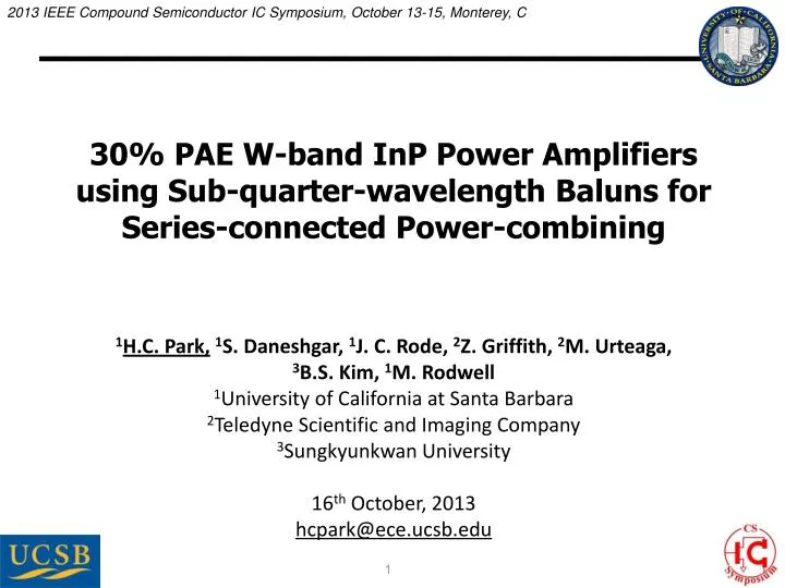
2013 IEEE Compound Semiconductor IC Symposium, October 13-15, Monterey, C. 30% PAE W-band InP Power Amplifiers using Sub-quarter-wavelength Baluns for Series-connected Power-combining.

E N D
2013 IEEE Compound Semiconductor IC Symposium, October 13-15, Monterey, C 30% PAE W-band InP Power Amplifiers using Sub-quarter-wavelength Baluns for Series-connected Power-combining 1H.C. Park,1S. Daneshgar, 1J. C. Rode, 2Z. Griffith, 2M. Urteaga, 3B.S. Kim, 1M. Rodwell 1University of California at Santa Barbara 2Teledyne Scientific and Imaging Company 3Sungkyunkwan University 16th October, 2013 hcpark@ece.ucsb.edu 1
mm-Wave Power Amplifier: Challenges mm-Wave PAs:applications: High resolution imaging, high speed communicationneeded: High power / High efficiency / Small die area ( low cost) Extensive power combining Compact power-combining Class E/D/F are poor @ mm-wave insufficient fmax , high losses in harmonic terminations efficiency must instead come from combiner Efficient power-combining Goal: efficient, compact mm-wave power-combiners 2
Parallel Power-Combining Output power: POUT = N x V x I Parallel connection increases POUT Load Impedance: ZOPT = V / (N x I) Parallel connection decreases Zopt High POUT→ Low Zopt Needs impedance transformation: lumped lines, Wilkinson, ... High insertion loss Small bandwidthLarge die area 3
Series Power-Combining & Stacks Parallel connections: Iout=N x I Series connections: Vout=N x V Output power: Pout=N2x V x ILoad impedance: Zopt=V/ISmall or zero power-combining lossesSmall die areaHow do we drive the gates ? Local voltage feedback: drives gates, sets voltage distribution Design challenge: need uniform RF voltage distribution need ~unity RF current gain per element ...needed for simultaneous compression of all FETs. 4
Standard λ/4Baluns: Series Combining Balun combiner:voltages add2:1 series connectioneach source sees 25 W→ double Imax for each source4:1 increased Pout Standardl/4 balun : l/4 stub→ open circuitlong lines→ high losseslong lines → large die 5
Sub-λ/4 Baluns for Series Combining What if balun length is <<l/4 ? Stub becomes inductive ! Sub-l/4 balun : stub→ inductivetunes transistor Cout !short lines→ low lossesshort lines → small die 6
Sub-λ/4Baluns for Series Combining 2:1 baluns: 2:1 series connection Each device loaded by 25W → HBTs are 2:1 larger than needed for 50W load. → 4:1 increased Pout. Sub l/4 balun: inductive stub balun inductive stub tunes HBT Cout. Similar network on input. 7
Sub-λ/4 Balun Series-Combiner: Design Each HBT loaded by 25W HBT junction area selected so that Imax=Vmax/25W Each HBT has some Cout . Stub length picked so that Zstub=-1/jwCout → tunes HBT 4:1 more powerthan without combiner. 8
Balun Configurations in PA ICs • Step 1 GND (M1) TRs • 2 (diff.) x 8 finger TR cells + GND (M1) 9
Balun Configurations in PA ICs • Step 2 GND (M1) GND (M1) CAP M2 TRs TRs CAP 10
Balun Configurations in PA ICs • Step 3 GND (M1) CAP M2 CAP TRs M3 • M2–M3 Microstrip transmission lines • But, E-fields between M3-M1 are not negligible !! 11
Balun Configurations in PA ICs CAP • Step 4 M3 sidewall sidewall TRs M2 GND (M1) CAP Walls M2-M3 CAP TRs M3 • M3–M1 E-field shield using sidewalls • Well-balanced balun with short length (λ/16) 12
2:1 Balun Test Results CP = 103fF FC = 81GHz I.L. = -1.1dB S21 = -1.76dB v1 Back-to-back measured S-parameters v2 CP = 78fF FC = 94GHz I.L. = -1.2dB S21 = -1.79dB CP = 65fF FC = 103GHz I.L. = -1.2dB S21 = -1.56dB v3 *Does not de-embed losses of PADs , capacitors, and interconnection lines 0.6~0.8 dB single-pass insertion loss (used for 4:1 power combining) 13
InP HBT (Teledyne 250nm HBT) cell: 0.25μm x 6μm x 4-fingers BVCEO = 4.5V , IC,max = 72mA Pout= 15.5dBm Ropt = 56Ω MAG/MSG including EM-Momentum results Emitters to GND Collector Base 350GHz fτ, 590GHz fmax@ JE=6mA/μm2 ~13dB MAG @ 85 GHz Courtesy: Teledyne Science Company 14
PA Designs Using 2:1 Balun Identical input / output baluns 2-stage input matching networks Active bias – thermal / class-AB 15
Single-Stage PA IC Test Results (86GHz) • 10dB Gain, >100mW PSAT, >30% PAE, 23GHz 3dB-bandwidth • Power per unit IC die area* =294 mW/mm2 (if pad area included) =723 mW/mm2 (if pad area not included) 16
Two-Stage PA IC Test Results (86GHz) • 17.5dB Gain, >200mW PSAT, >30% PAE • Power per unit IC die area* =307 mW/mm2 (if pad area included) =497 mW/mm2 (if pad area not included) 17
800 mW 1.3mm2 Design Using 4:1 Baluns • Baluns for 4:1 series-connected power-combining • 4:1 Two-Stage Schematic • 4:1 Two-Stage Layout (1.2x1.1mm2) Small-signal data looks good. Need driver amp for Psat testing. 18
Sub-λ/4 Baluns for Series Combining Series combining using sub-l/4 baluns Low-loss (~0.6 dB @85GHz) → high efficiency Compact→ small die area2:1 baluns→ effective 2:1 series connection 4:1 increase in output power. W-band power amplifiers using 2:1 baluns Record >30% PAE @ 100mW, 200mW Record 23 GHz 3-dB bandwidth Record 723mW/mm2 power density Completed new designs in test Higher-efficiency ~200 mW, 85 GHz designs 4:1 balun design: goal 800 mW, 85 GHz, 1.3 mm2 220 GHz 4:1 balun design has been taped out • 450 x 820 um2 825 x 820 um2 19
Thanks for your attention! Questions? hcpark@ece.ucsb.edu