Download
1 / 40
400 likes | 523 Views
Potential Advantages of Digitally Sampling Scintillation Pulses in Timing Determination in PET. Qingguo Xie 1,2 , Chien-Min Kao 1 , Xi Wang 2 , Ning Guo 2 , Caigang Zhu 2 , Henry Frisch 3 , William W. Moses 4 , and C.-T. Chen 1

E N D
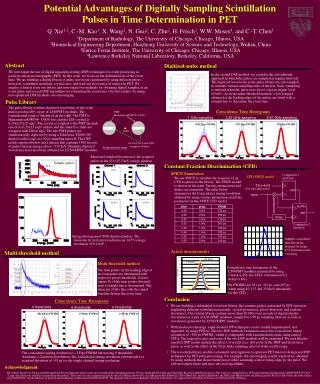
Potential Advantages of Digitally SamplingScintillation Pulses in Timing Determination in PET Qingguo Xie1,2, Chien-Min Kao1, Xi Wang2, Ning Guo2, Caigang Zhu2, Henry Frisch3, William W. Moses4, and C.-T. Chen1 1Department of Radiology, The University of Chicago, Chicago, IL, USA 2Department of Biomedical Engineering, Huazhong University of Science and Technology, Wuhan, Hubei, China 3Enrico Fermi Institute, The University of Chicago, Chicago, IL, USA 4Lawrence Berkeley National Laboratory, Berkeley, California, USA
Pulse LibraryHRRT Module The HRRT detector head contains an array of 9 by 13 crystal blocks that are coupled to an array of 10 by 14 photomultiplier tubes (PMTs) by using the PMT-quadrant-sharing configuration (PQS). Each crystal block of the HRRT is made of 8x8 double-layered LSO/LYSO phoswich scintillators.
Pulse LibraryHRRT Module The prototype consists of two HRRT (High Resolution Research Tomograph) detector heads. The spacing between detectors shown is ~6 cm, which is adequate for imaging rodents. HRRT Detector Heads A single double-layered, 8 x 8 LSO crystal block affixes onto 4 photomultiplier tubes in the quadrant-sharing configuration.
MPPC Principle Equivalent circuit An MPPC having 100 microcellsHamamatsu S10362-11-100C Sample 171
Datasets • Dataset 1 • Bill’s Module • 1500 pulses • LLD:~370keV • Dataset 2 • Bill’s Module • 9000 pulses • LLD:~90keV
Coincidence Timing Resolution350 keV, 4 Thresholds, 312 ps FWHM 4Thresholds, FWHM=312ps Threshold_Ch2=40mv, 90mv, 140mv, 190mv Threshold_Ch1= 216/267*Threshold_Ch2
Coincidence Timing Resolution350 keV, 6 Thresholds, 296 ps FWHM 6 Thresholds, FWHM=296ps Threshold_Ch2=40mv, 70mv, 100mv, 130mv, 160mv, 190mv Threshold_Ch1= 216/267*Threshold_Ch2
Coincidence Timing Resolution350 keV, 8 Thresholds, 291 ps FWHM 8 Thresholds, FWHM=291ps Threshold_Ch2=40mv, 60mv, 80mv, 100mv, 120mv, 140mv, 160mv, 180mv Threshold_Ch1= 216/267*Threshold_Ch2
Coincidence Timing Resolution350keV and 400keV # Thresholds 350keV 400keV 4 312ps 304ps 6 296ps 288ps 8 291ps 283ps Dataset 2: 350keV, 3579 pulse pairs 400keV, 3140 pulse pairs
Coincidence Timing ResolutionEnergy Groups Ch2 En1 En2 En3 Ch1 En1 250ps 305ps 303ps En2 273ps 293ps 283ps En3 244ps 295ps 250ps En1: 400-486 En2: 486-536 (+-5%) En3: >536
Coincidence Timing ResolutionFixed Time Digitized Pulse Fitting
Coincidence Timing ResolutionFixed Time Digitized Pulse Fitting
Coincidence Timing ResolutionCFD TH FWHM 085keV 341ps 175keV 313ps 350keV 297ps
Coincidence Timing ResolutionSoftware CFD ~308 ps @ 0.2, 1.6ns for 370keV using dataset 1
Discussion • Timing resolution obtained from digitized pulses is comparable to analog CFD. • Efficient calibration, especially system level for TOF PET • Benefits for PET: Position, Energy, Time, and Count-rate • Advanced algorithms • Dependence between shapes and scintillators, energy (Average Pulse Fitting, slightly better timing resolution, pulse simulation, Monte Carlo, pattern reconzation) • Noise pattern
Acknowledgement • Collaborators: • Bo Zhang • Robert Wagner • Gary Drake • John Anderson • Camden D. Ertley • Jean Francois • Patrick LeDu • Christophe Royon • Joy Lin • Octavia • Fukun Tang • Seungryong Cho • Jeffrey S. Souris • Qian Zhang • Shuijin Su • Zheng Tian