1 / 56

TESTING 4-BIT-ADDER BY COUNTER AND WALKING ONES

TESTING 4-BIT-ADDER BY COUNTER AND WALKING ONES. GROUP MEMBERS: DIEU-NHI LE (4-Bit-Adder) STEPHEN LAM (Shift Register) BAO DOAN (Counter) CHAU HOANG (Counter). SPECIFICATIONS. Timing: Speed: Power: Shift Register Adder: P=20.1mW Counter Adder: P=20.5mW Total area:

velvet
Download Presentation

TESTING 4-BIT-ADDER BY COUNTER AND WALKING ONES

An Image/Link below is provided (as is) to download presentation Download Policy: Content on the Website is provided to you AS IS for your information and personal use and may not be sold / licensed / shared on other websites without getting consent from its author. Content is provided to you AS IS for your information and personal use only. Download presentation by click this link. While downloading, if for some reason you are not able to download a presentation, the publisher may have deleted the file from their server. During download, if you can't get a presentation, the file might be deleted by the publisher.

E N D

Presentation Transcript


  1. TESTING 4-BIT-ADDER BY COUNTER AND WALKING ONES GROUP MEMBERS: DIEU-NHI LE (4-Bit-Adder) STEPHEN LAM (Shift Register) BAO DOAN (Counter) CHAU HOANG (Counter)

  2. SPECIFICATIONS • Timing: • Speed: • Power: Shift Register Adder: P=20.1mW Counter Adder: P=20.5mW • Total area: Shift Register Adder: A=0.13um^2 Counter Adder: A=0.076um^2

  3. 4-BIT-ADDER - Testing 1-Bit, layout. • Testing 4-Bit, layout. • Verify the logic using Verilog.

  4. 1-BIT ADDER SCHE.

  5. 1-BIT ADDER LAYOUT

  6. 1-BIT ADDER EXTRACTED VIEW

  7. 1-BIT ADDER LVS

  8. 1-BIT-ADDER-TRANSIENT RESPONSE

  9. 1-BIT ADDER VERILOG

  10. 1-BIT ADDER TEST BENCH

  11. 4-BIT ADDER TEST BENCH

  12. 4-BIT ADDER LAYOUT

  13. 4-BIT ADDER EXTRACTED VIEW

  14. 4-BIT ADDER LVS

  15. 4-BIT ADDER TRANSIENT RESPONSE

  16. 4-BIT ADDER VERILOG

  17. NAND3 SCHEMATIC

  18. NAND3 LAYOUT

  19. NAND3 EXTRACTED VIEW

  20. NAND3 LVS

  21. NAND3 TRANSIENT RESPONSE

  22. NAND3 TEST BENCH

  23. TRUTH TABLE FOR 7474 D FLIP-PLOP 0 = low 1 = high X = irrelevant ↑ = low – to – high transition of the clock pulse

  24. 1 BIT D FLIP FLOP SCHEMATIC

  25. 1 BIT D FLIP FLOP LAYOUT

  26. 1 BIT D FLIP FLOP EXTRACTED VIEW

  27. 1 BIT D FLIP FLOP LVS

  28. 1 BIT D FLIP TRANSIENT RESPONSE

  29. 1 BIT D FLIP TEST BENCH

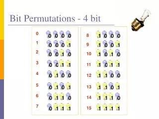
  30. 0100 1110 1100 1101 0011 1000 1001 1010 1111 0110 0101 0111 0010 1011 0001 0000 4-BIT BINARY COUNTER • A four bit binary counter we have designed in this project counts down and with every clock input moves up to the next higher state. It was designed using D type flip-flops. It has a SET signal which is setting when it is equal to 1.A CLEAR signal sets the counter back to 0.

  31. COUNTER SCHEMATIC

  32. COUNTER LAYOUT

  33. COUNTER EXTRACTED VIEW

  34. COUNTER LVS

  35. COUNTER TRANSIENT RESPONSE

  36. COUNTER TEST BENCH

  37. COUNTER ADDER SCHEMATIC

  38. COUNTER ADDER LAYOUT

  39. COUNTER ADDER EXTRACTED VIEW

  40. COUNTER ADDER LVS

  41. COUNTER ADDER TRANSIENT RESPONSE

  42. COUNTER ADDER TEST BENCH

  43. 4 BIT SHIFT REGISTER SCHEMATIC

  44. 4 BIT SHIFT REGISTER LAYOUT

  45. 4 BIT SHIFT REGISTER EXTRACTED VIEW

  46. 4 BIT SHIFT REGISTER LVS

  47. 4 BIT SHIFT REGISTER TRANSIENT RESPONSE

  48. 4 BIT SHIFT REGISTER TEST BENCH

  49. 4 BIT SHIFT REGISTER ADDER SCHEMATIC

  50. 4 BIT SHIFT REGISTER ADDER LAYOUT

More Related