Download
1 / 21
210 likes | 300 Views
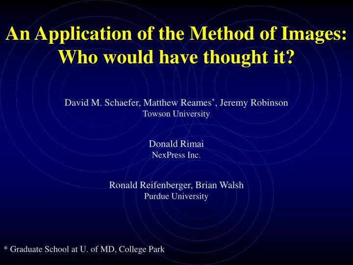
An Application of the Method of Images: Who would have thought it? David M. Schaefer, Matthew Reames * , Jeremy Robinson Towson University Donald Rimai NexPress Inc. Ronald Reifenberger, Brian Walsh Purdue University * Graduate School at U. of MD, College Park. Outline.

E N D
An Application of the Method of Images: Who would have thought it? David M. Schaefer, Matthew Reames*, Jeremy Robinson Towson University Donald Rimai NexPress Inc. Ronald Reifenberger, Brian Walsh Purdue University * Graduate School at U. of MD, College Park
Outline • 1. What is “The Method of Images”? • Atomic Force Microscopy • Description of our experiment • Analysis and Results
Method of Images Solving electrostatic problems involves solving Laplaces Equation, assuming appropriate boundary conditions. 2 V = 0 Uniqueness Theorem: The solution to Laplace’s equation in some Region is uniquely determined if the value of V is specified on all Boundaries of the region If we can guess at a solution to Laplaces eqn, and it Satisfies all boundary conditions, then it is THE solution.
Classic Image Problem z z q q d d y y d V= 0 x x -q Solution: Suppose a charge q is held a distance d above an infinite grounded conducting plane. What is the potential in this region?
Scanning Probe Microscopy I. Scanning Tunneling Microscope II Atomic Force Microscope Derivative Microscopes Kelvin Probe Capacitance Magnetic Force Friction Force Electrochemical General Operation of SPMs
Position Sensitive Detector Computer Control (Feedback) Cantilever ATOMIC FORCE MICROSCOPE DESIGN Diode Laser Sample AFM Image
Nanotechnology Lab at Towson • Two Commercial SPMs • One Home built SPM
Force Measurements with the AFM Loading Approach Jump to Contact Work of Adhesion Force of Removal Forces: Van der Waals Electrostatic Adhesion Elastic Modulus Plasticity
Our Experiment Purpose – To study electrostatic interactions and charge transfer between micron size particles and materials. AFM Cantilever Charged Particle (4.7 micron radius) Surface
Micromanipulator View from CCD Camera CCD Camera Micromanipulator Attachment of particles to the cantilever tip
Particle Attachment A picture captured by the CCD Camera shows how the particle was maneuvered onto the tip. Once the particle was picked up by one of the tungsten tips and glue was applied to the cantilever tip; the particle was carefully moved onto the cantilever tip. When the particle is on the cantilever tip, a UV light source is incident on the cantilever so the glue will cure. Once cured, the final product is a cantilever tip with a particle attached; as seen below
UV Source E UV Light : Off V Surface 0 UV Light : Off V surface: 0 UV Light : On V Surface 0 No Charge on Sphere Sphere Polarized Sphere Polarized How do you control the Charge on a Micron Size Particle? Photoconducting sphere and substrate
Force Measurement Procedures • 1. Charge the sphere: • Turn on UV Source, no sample voltage • Apply a voltage to the sample • E field induces a charge separation in sphere • Turn off UV Source, locking in charge in sphere • Set surface potential to zero • 2. Perform Force measurement: • Sample is moved up to sphere until a specified force is obtained • The sample then immediately is withdrawn to original position • 3. Sphere is neutralized: • UV Light is turned on for 30 sec. (surface potential still 0) 4. Perform Force measurement
Results AMT 2 AMT 1 Initial Charging w/ V = -20V. Slight long range interaction observed. Neutralization of charge. No long range interaction observed.
Results: Force Curves AMT 5 (V = -58.64 V) AMT 3 (V=-39.06 V) AMT 7 (V = -78.20 V) AMT 9 (V = -97.8 V)
z ro x z Analysis of Long Range Attraction Determining the position of image Using Method of Images
Long Range Interactions Distance nm 0 -25 AMF 9 -50 N n -75 e c r o F -100 -125 -150 -175 0 100 200 300 400 Distance nm q=3.58719*10^-16 C
Long Range Interactions Distance nm 0 -25 AMF 7 -50 N -75 n e c r o -100 F -125 -150 -175 0 100 200 300 400 Distance nm q=3.090703*10^-16 C
Long Range Interactions Distance Distance nm nm 0 0 -25 AMF 7 -20 -50 -40 -75 N n N n e c e -60 r -100 c r o o F F -125 -80 -150 -100 -175 -120 0 100 200 300 400 Distance nm 0 100 200 300 400 Distance nm AMF 5 q=2.1861*10^-16 C
Charge vs Voltage 4.00E-16 Voltage (V) Charge (C) 3.50E-16 3.00E-16 2.50E-16 Charge C 2.00E-16 1.50E-16 1.00E-16 5.00E-17 0.00E+00 -120 -100 -80 -60 -40 -20 0 Voltage V From Theory Slope = 2.2 0.2 x 10⁻¹⁸ q = 1.65 x 10⁻¹⁸ * V Is the Charge Consistant with our Model? If the charge, found by fitting our curves, is correct, we would expect the charge to vary linearly with the applied voltage.
Conclusions • A novel method of producing controllable amount of charge • on a micron size particle has been produced. • By fitting force curves with a simple theory based on the method • of images, the charge on the sphere was determined. • The charge follows a simple theory which predicts linearity in the • charge vs. voltage plot, with the slope approximately as expected. • These results have consequences for the contribution of electrostatics • to adhesion of nanometer –scale contacts.