Download
1 / 69
780 likes | 1.16k Views
OFC Based Signaling systems. Dy. CSTE/CON/SC. 1. A signal is a device to communicate to Loco Pilot to go ahead or stop. Signalling system facilitates the safe and efficient movement of trains on the railway. ROLE OF SIGNALLING IN RAILWAYS. 2. Key Lock Inter locking.

E N D
OFC Based Signaling systems Dy. CSTE/CON/SC Dy.CSTE/Con/SC
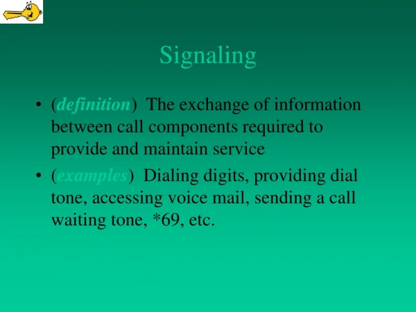
1 • A signal is a device to communicate to Loco Pilot to go ahead or stop. • Signalling system facilitates the safe and efficient movement of trains on the railway. ROLE OF SIGNALLING IN RAILWAYS
2 Key Lock Inter locking The human element : • Setting of the point and locking is entirely manual through key and lock system. • Signals controlled by levers situated at the signals.
3 Mechanical Signaling • Operation of Points and Signals from a fixed location with group of levers through rigid connection (Rod / Wire) • System is interlocked mechanically by grouping the levers.
4 Electrical Signaling Panel Interlocking • Signals controlled by Operation from a Panel through cables by electrical means. • Each function to be operated individually • Interlocking is achieved through relays.
5 Route Relay Interlocking • Individual operation is avoided. • Final function is achieved though pre-defined automatic operation .
6 IBS / Automatic signaling • IB / Automatic Signaling enhances the section capacity • Automatic signals are self controlled and avoids human operations
7 Electronic Interlocking • Operation is done through computer or Panel • Microprocessor based interlocking system • Interlocking is achieved through Software.
8 Modern signaling • TPWS: Automatic train protection and prevents collision. • Avoids SPAD cases. • Transmits advance information to the Driver & controls the engine.
9 Advanced Signaling • ATC-Automatic Train Control., CTC –Centralized Traffic Control, Moving Block and Radio Block.
OUTLINE on OFC based systems • Intermediate Block signals on OFC using EI. • Intermediate Block Signals on OFC using UFSBI. • OFC based EI working on remote/local operation. • OFC based auto signaling. • OFC based ASM-LC Gate Voice logging system. • OFC based SP/SSP for Remote Control • Commercial exploitation on Passenger Amenities Dy.CSTE/Con/SC
OFC Based IBS using EI Dy.CSTE/Con/SC
COMMUNICATION FACILITIES REQUIRED AT IBS UP IB PHONE UP IB AC UP IB BPAC DN IB BPAC RESET UP IB RESET 6 QUAD 6 QUAD STN-A IB ROOM STN-B RTU UP IB BPAC RESET DN IB RESET DN IB AC DN IB BPAC DN IB PHONE OFC FROM STATION TO STATION Dy.CSTE/Con/SC
COMMUNICATION FACILITIES CAN BE EXTENDED THROUGH OFC UP IB PHONE UP IB AC UP IB BPAC DN IB BPAC RESET UP IB RESET ALTERNATE OFC ALTERNATE OFC STN-A IB ROOM STN-B RTU UP IB BPAC RESET DN IB RESET DN IB AC DN IB BPAC DN IB PHONE OFC FROM STATION TO STATION Dy.CSTE/Con/SC
PROTOCOLS • IB PHONE: VOICE COMMUNICATION • IB UNIVERSAL AXLE COUNTER: 2 wire E&M. • IB DIGITAL AC: V.21 modem communication (2 wire). • IB BPAC: V.21 modem communication (2 wire). • IB RESET MODEM: V.21 modem communication (2 wire). • RTU: Analog Channel of OFC, digital microwave and analog microwave or 64KBPS data channel on OFC or digital microwave ( 4 wire E&M) Dy.CSTE/Con/SC
INTEGRATION OF COM EQUIPMENT AT IBS • MODEL-1: • Using Existing STM-1’s and PD Muxes • MODEL-2: • Using Dark fibers • RAD Make MP 2104. • Moxa Make Manageable Switch EDS-405A/408A Series Dy.CSTE/Con/SC
Model-1Using Existing STM-1 2 Port STM-1 2 Port STM-1 EXISTING OFC STN-B STN-A IBS ADD THIRD PORT PD MUX PD MUX NEW OFC PD MUX Dy.CSTE/Con/SC
Model-1Using Existing STM-1 • Drawbacks: • Dependent on existing power supply at OFC Huts. • Reliability of STMs and PDMUX for safe communication. • Copper working between OFC Hut to Relay Room. • Advantages: • Remote Management of STMs. • Alternate Path for existing telecommunication. Dy.CSTE/Con/SC
Model-2 Dark Fiber Dy.CSTE/Con/SC
SPLIT CARD FILE AT IBS Dy.CSTE/Con/SC
Integration of signaling EI- A1 EI – A2 • One EI unit can maintain two discrete redundant network links: • Step 1: Data packet ‘P1’ delivered by EI - A1 is duplicated and transmitted on Comm board ports E1 & E2 • Step 2: EI – A2 Ethernet Port E2 receives data packet ‘P1’ before Ethernet Port E1 • Step 3: When EI – A2 Ethernet Port E1 receive data packet ‘P1’ it is discarded due to duplicate ID P1 P1 COMMS BOARD COMMS BOARD E1 Network - A E1 Packet Discarded P1 P1 P1 P1 P1 P1 E2 E2 Network - B Guntakal Division
COMPLETE SCHEME Dy.CSTE/Con/SC
Electronic Interlocking (EI) split card file Dy.CSTE/Con/SC
EDS 408A Switches and NPort 5650I-8-DT Dy.CSTE/Con/SC
Front View of EI Card file, Multiplexer and FMS in a rack. Dy.CSTE/Con/SC
Panel Indications to ASM regarding redundant system failure even at IBS and fiber break with alarm. Dy.CSTE/Con/SC
Front view of the entire rack at Srikalahasthi station. Dy.CSTE/Con/SC
Manageable Switch EDS-408A Series 2. Terminal block for power input 6. Power input PWR1 LED 7. Power input PWR2 LED 8. Fault LED 9. MSTR/HEAD: LED indicator 10. CPLR/TAIL: LED indicator 11. 10/100BaseT(X) ports 12. TP port’s 100 Mbps LED 13. TP port’s 10 Mbps LED 14. 100BaseFX ports 15. 1 FX port’s 100Mbps LEDs 16. Model Name Guntakal Division
Manageable Switch EDS-408A Series 1.Grounding screw 2. Terminal block for power input 3. Console port 4. DIP switches 5. Heat dissipation vents 17. Screw hole for wall mounting kit 18. DIN-Rail kit MTBF: 11,02,845 hrs Warranty: 5 years Guntakal Division
Remote Monitoring UnitN Port 5650I-8-DT Dy.CSTE/Con/SC
RAD Make MP 2100 Guntakal Division
MP 2100 GENERAL VIEW • 16 SLOTS • ADAPTIVE TIMING FACILITY. CRYSTAL OSCILLATOR WITH 32PPM. • POWER: 230/110 V AC, -48V/24V DC (INTERNAL JUMPER SELECTION) • REDUNDNACY: One logic/power card can be removed while working. Guntakal Division
MP2100 REAR VIEW Guntakal Division
MP 2100 POWER SUPPLY Guntakal Division
MP 2100 CONTROL SUBSYSTEM • REPLACING CL CARD DURING FAILURE: • STAND BY CARD CAN BE REPLACED WITH OUT DISRUPTING SERVICES. • FIRST FLIP TO STANDBY MODULE BEFORE REPLACING ONLINE MODULE. RS 232 FOR SYSTEM MANAGEMENT ETHERNET PORT Guntakal Division
Cost Analysis Existing system Proposed System Typical section length: 12KM Guntakal Division
Failure Analysis As Per SFR • One failure for Past 20 Months. • Commissioned in Nov-2012. 17.04.2013: Up IB Axle Counter Failed. Reason: VR relay Contact Problem. Dy.CSTE/Con/SC
Failure Analysis IB Passing at Danger Dy.CSTE/Con/SC
Issues need to be addressed • How to bring reset command? • Addition or modification of logic during redundant axle counters, IB circuit modification. • MP2104 to be replaced with MP2100 for complete security. • Hot Stand by conversion is not done. Dy.CSTE/Con/SC
Why reliability is achieved? • Failure rate is proportional to number of components required to be function with in their characteristics. • Normally 12 pairs of signalling cable, 4 pairs of 6 quad cable, power cable is required to be available round the clock for working of IB. This will increase the probability of failure. With OFC only two pairs are required and when path redundancy is provided the probability is also reduced by ½. Dy.CSTE/Con/SC
OFC Based IBS USING UFSBI Dy.CSTE/Con/SC
OFC Based IBS using UFSBI Dark Fiber ECAT ECAT MAPLE 4C Main link Fiber MAPLE 4C HA SSDAC HA SSDAC HA SSDAC HA SSDAC Or / Dual SSDAC Relay Inputs 16 In / 16 Out UFSBI UFSBI Protection Path OFC Dy.CSTE/Con/SC
Cost Analysis Existing system Proposed System Typical section length: 12KM Guntakal Division
4 E1 uplink Slot 1 Slot 2 Slot 3 MAPLE-4C Front and Back Plane MAPLE 4C Front Panel E1’s LED indicationConsole SNMP Port MAPLE 4C Back Panel Max. FXO/FXS channels : 30, Max E&M channels : 24, Max V.35 channels : 3 Dy.CSTE/Con/SC
E CAT-01 Black Plane FRONT PANEL – ECAT 01L LED Indications Ethernet Port BACK PANEL – ECAT 01L OFC up links E1 Ports Dy.CSTE/Con/SC
Little View NMS • Windows-Package based Centralized Network • Management Application to manage • MRO-TEK TDM products family • Java based compliant system supporting • SNMPv1, v2c and v3 standards • Client-Server architecture (Multiple clients can access a single server simultaneously) • Highly scalable for growing networks (Manages up to 20000 nodes) Dy.CSTE/Con/SC
OFC based EI working on remote/local operation Dy.CSTE/Con/SC
Centralized and Distributed Architecture of EIs • Reference: TAN No. STS/E/TAN/3008 dated 31.03.2014. • Distributed architecture for EI shall be adopted by IR for Interlockings with more than 50 routes while centralized architecture may be used for interlocking routes upto 50. Dy.CSTE/Con/SC
Centralized and Distributed Architecture of EIs • For Green field Projects: • New line, doubling, gauge conversion. • Centralized EI with OCs at way side stations may be used which shall have provision of local as well as centralized operation. Dy.CSTE/Con/SC
Centralized and Distributed Architecture of EIs • For up gradation of interlocking on branch lines with Object controllers at way side stations and signal controlling VDU from signal control centre for operation. Dy.CSTE/Con/SC