Download
1 / 39
430 likes | 752 Views
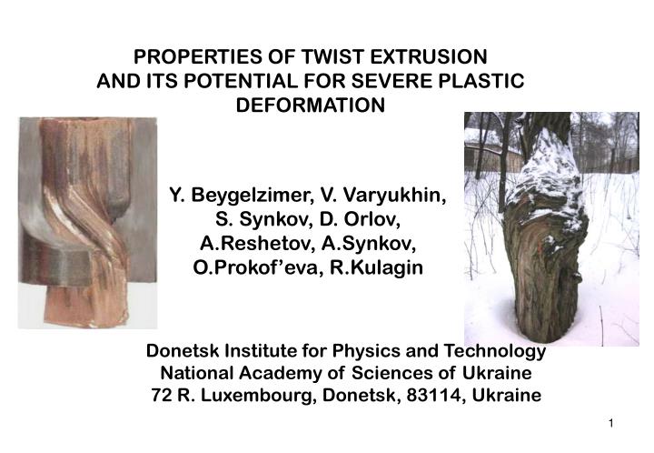
PROPERTIES OF TWIST EXTRUSION AND ITS POTENTIAL FOR SEVERE PLASTIC DEFORMATION. Y. Beygelzimer, V. Varyukhin, S. Synkov, D. Orlov, A.Reshetov, A.Synkov, O.Prokof’eva, R.Kulagin. Donetsk Institute for Physics and Technology National Academy of Sciences of Ukraine

E N D
PROPERTIES OF TWIST EXTRUSION AND ITS POTENTIAL FOR SEVERE PLASTIC DEFORMATION Y. Beygelzimer, V. Varyukhin, S. Synkov, D. Orlov, A.Reshetov, A.Synkov, O.Prokof’eva, R.Kulagin Donetsk Institute for Physics and Technology National Academy of Sciences of Ukraine 72 R. Luxembourg, Donetsk, 83114, Ukraine
Twist Extrusion: Why care? Kinematics of TE is substantially different from that of other SPD processes (like ECAP and HPT). New potential for investigating and forming new structures with new properties.
Experimental investigation of TE kinematics 1. We used experimental vizioplasticity method (E. G.Thomsen). Metal flow were reconstructed from cross-sections of the specimen with fibres stopped in the die. 1 5 2. We refined this method by incorporating two natural conditions: -metal volume remains constant; -metal flow is limited by the surface of the die. 25 30 Advantage: method takes into account the actual rheology of metal and real friction conditions.
Main Findings • As in HPT and ECAP, deformation in TE is performed through simple shear. • There are multiple shear planes, unlike in HPT and ECAP. These planes are perpendicular and parallel to the specimen axis. • There are vortex flow with stretching and mixing within the deformation centre • There are four well defined deformation zones with different properties of metal flow
T T T T 1 2 Deformation Zones 1 and 2 Located at the two ends of the twist part of the die. Simple shear in the Transversal plane (T)as in HPT. Shears in zones 1 and 2 have opposite direction. Strain: from e ~ 0.0 on the axis to e ~1.0 ÷1.5 on the periphery
Strain accumulation Zones 1 and 2 Cu, 20oC 2 1 Strain accumulation along the die in a characteristic point where zones 1 and 2 are responsible for most of the deformation.
1 2 3 L L =250 300 Deformation Zone 3 Located in the twist part of the die between zones 1 and 2 Simple shear in therotating Longitudinal plane (L) = 250 300 Strain: e ~ 0.4 0.5
Strain accumulation Zones 3 Cu, 20oC 3 Strain accumulation along the die in central point where zone 3 is responsible for the deformation.
4 Deformation Zone 4 Located in the twist part of the die between zones 1 and 2 Simple shear in the peripheral layer (1÷2 mm thick) Al-0.13%Mg Al-0.13%Mg Strain: e ~ 2 We thank Dr. Berta (University of Manchester, UK) for macrostructures b), c)
Strain accumulation Zone 4 Cu, 20oC 4 Strain accumulation along the die in a peripheral point
Controlling metal flow in TE Strain distribution and deformation zones boundaries strongly depend on • the geometry of die’s cross-section, • inclination angle • rotation angle By varying these parameters, one can obtain given inhomogeneous strain. This is of interest for(1) investigating the effects of strain gradient on the evolution of material structure, as well as (2) obtaining gradient structures.
Accumulation strain for 1 pass TE (Cu, 20oC) =35o, =80o =50o, =80o =50o, =80o =50o, =80o
0,2 , МPа 0,2 , МPа Smoothing of structure and properties during maltipass TE Despite the nonuniformity of deformation, subsequent TE typically leads to uniform structure and properties. This is due to (1) mixing of metal and (2) stabilization of structure and saturation of properties if strain becomes greater than saturation level es Cu 99,9% After 2 passes After 4 passes Joint work with Dr. Korshunov, Sarov, Russia
es 99.9%Cu es Stabilization of structure and saturation of propertiesduring TE 99.99% Al Joint work with Dr. Korshunov, Sarov, Russia 1 TE pass 4 TE passes Joint work with Prof. Horita, Kyushu University, Fukuoka, Japan
Zone where strain is above the saturation thresholdes=2 (1pass) e
Zone where strain is above the saturation thresholdes=2 (2pass) e
Zone where strain is above the saturation thresholdes=2 (3 pass) e
Zone where strain is above the saturation thresholdes=2 (4pass) e
Zone where strain is above the saturation thresholdes=2 (5pass) e
Two main routes of TE Two orientations of the die (, ) lead to two main routes of TE CD Route I: CD+CD CD CCD Route II: CD+CCD CD-clockwise die CCD- counterclockwise die
T A Two main routes of TE Route I: CD+CD Route II: CD+CCD Plane T Plane T T 2A L L Plane L Plane L 0 0 1 2 1 2 Number of passes Number of passes , (16)
CP-Ti (grade 2) 300oC =45o Different loading paths can lead to different structures and properties. In particular, using route II allows one to increase the yield threshold of Ti after it saturates in route I Route I Route II , , Joint work with Prof. Rack, Clemson University, USA Route II overcomes saturation
Vortex and Mixing Deformation Zones 3 and 4 form a vortex-like flow which stretches metal particles. The stretching increases with subsequent TE passes as long as the dies have a constant direction (all clockwise or all counter-clockwise) perpendicular cross-section
Вытягивание Stretching (1 pass, counter-clockwise die)
Вытягивание Stretching (2 passes, counter-clockwise die)
Вытягивание Stretching (3 passes, counter-clockwise die)
2 mm Passes with alternating directions create folds CD CCD , We thank Dr. Milman for sharing the microstructure.
At a finer scale, folds form due to instability of shear planes After one pass TE Initial Aluminum Joint work with Prof. Milman, Kiev, Ukraine
Alternating stretching and folding leads to mixing, as in Smale’s horseshoe Initial specimen stretching folding Final specimen After several passes
TE has already been successfully used to obtain UFG structure with good properties in Al, Cu, Ni and Ti alloys (more at http://hunch.net/~yan). • Most importantly, TE opens new possibilities for investigating and forming new structures with new properties, mainly due to four factors.
L T Factor 1: Two new shear planes in the volume of the specimen TE ECAP
Factor 2: Vortex-like flow with stretching and mixing of metal particles This is of interest for (1) homogenization (2) mechanochemical reactions
Factor 3: Two main routes of TE which can be combined with any SPD or metal forming processes (for example: ECAP, rolling, extrusion) to broaden the space of possible loading paths. ECAP TE A I B C II BA BC
Factor 4: New technological possibilities ECAP TE Obtainingprofile or hollow specimen Metal waste reducing Twist die F
We hope that TE will find its place among other SPD techniques
We hope that TE will find its place among other SPD techniques If anyone wants to talk about TE, tean@an.dn.ua