Download
1 / 19
190 likes | 301 Views
First Light AO system (FLAO) status & future plans. Presented by: S. Esposito. The Arcetri AO group. First Light AO system.

E N D
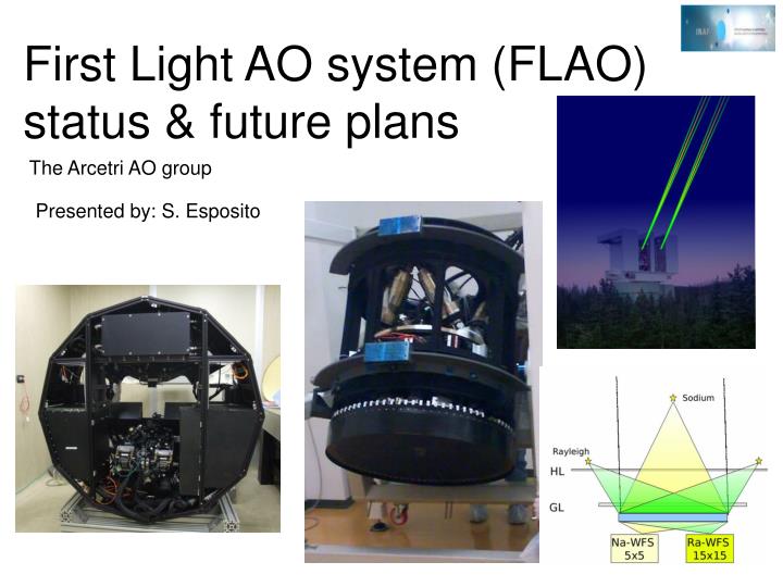
First Light AO system (FLAO) status & future plans Presented by: S. Esposito The Arcetri AO group
First Light AO system The first light AO system is coupled to the LUCIFER facility instrument: a seeing & diffraction limited NIR (1-2.5 mm) imager and spectrograph located at the front bent Gregorian focal station. The two FLAO key components: -A deformable secondary with 672 acts. -A Pyramid WFS with up to 30x30 subap.
Adaptive secondary mirrors -Use of adaptive secondaries allows to improve optical efficiency and simplify the optical set-up of any AO system. Infact no coupling optics is required between DM, WFS and scientific instrument. -The deformable secondaries are available for all telescope instruments. System main data -672 actuators -<1ms rise time -RTC computation hexapd Control electronic Cold plate Back plate
LBT672a acceptance Mech. Acceptance (ADS) Electrical acceptance (MG) Optical acceptance (Arcetri)
Mirror modes settling time Mode #4 Mode #147 Settling time: Below 0.8ms for all mirror modes up to 45 deg elevation. 56% modes match goal with elevation ≥45° Spec: baseline 1.5ms, goal 0.7ms
28nm residual Un plot dei tempi di risposta ? Cold test 50nm residual Turbulence correction performance A set of commands corresponding to turbulence evolution is sent to the actuators. Then the capacitive sensors output is compared with the original comands. Turbulence conditions and requirements seeing: 0.65arcsec L0: 200m ;v wind: 15m/s spec: baseline 50nm rms, goal 28nm rms Baseline matched: correcting 360 modes Goal matched: correcting 590 modes Optical test in progress @ Arcetri: 1) Mirror flattening 2) Influence functions measurements
PS SH Pyramid & SH sensor Numerical simulation of closed loop performance of the LBT FLAO system comparing Pyramid and SH sensor. Strehl ratio plot as a function of guide star magnitude in R band for Pyramid Sensor (PS) and Shack-Hartmann sensor (SH). PS is less sensitive to uncorrected atmospheric perturbations. Energy left In the PSF halo is 1/3 for PS enabling higher PSF contrast. PS achieve the same performance with a star about 1 mag fainter.AO system sky coverage is doubled (5%-10% K band, GP). Strehl Ratio in seeing limited case (8m tel.)
Acquisition & guiding unit Wavefront sensing unit The Ws unit (#1 & #2) Una vista 3d in cui si riconoscono le tre scatole W#1 after acceptance test in June08
WFS unit The lab set-up for AO system test Closed loop lab test of the AO system (Jun06) 45-actuator prototype The 45 actuators prototype of deformable secondary
Closing the loop with 666 actuators at ESO (June08) Pupil images on the LLLCD In closed loop Pyramid sensor main parameters 31x31 subapertures Modal control with 667 Frame rate 80Hz Eq. wind speed 3m/s 2 phase screens no slope null vector is used PSF profiles Red: ideal Black: lab Corrected H band PSF SR > 0.93 8.5e3 5000counts/sub/dt Wf rms reduced more then factor 10 1e1 PSF contrast at ~ 0.1 arcsec from center is 1e3
FLAO systemtest @ Arcetri Closed loop test configuration F/15 beam from ref. source. 13700mm Lab
0.32” 0.62” GLAO system & FLAO Future plans “The wide field capabilities of LUCIFER MOS and imaging, lead to unique observations when combined with GLAO.” [GLAO blue book] PI S. Rabien The ARGOS GLAO system under study corrects for low altitude turbulence using 12 km altitude Raileigh sources. The GLAO correction is equivalent to an improvement of the statistic of r0 (see plot). At the mean of the distribution the FWHM is reduced with GLAO from 0.63 to 0.34 in K-band.
GLAO upgrade path I “identify upgrade path to on-axis diffraction limited performance (=SCAO)” [LBT LGS phase A study] Options for GLAO upgrade path to diffraction limited images over small FoV: 1) tomography with dynamical ref. (UoA) 2) Low power Na laser WFS (INAF/Arcetri). “The central point stands in the observation that the turbulence of the high layers, the ones not sampled by the GLAO, is weaker of the ground layer turbulence and can be corrected using a smaller numbers of modes. This allows using larger subapertures that in turn means a reduced laser power to get a sufficient number of photons per frame.” [LBT LGS phase A study]
GLAO upgrade path II Estimating the number of corrected modes for DL performance: Each cell contains: (top) the effective r0 [m] of high layers un-sampled by GLAO system and (bottom) the number of modes corrected by the high layer sodium AO to get 0.5 rad residual. A 20 modes correction is enough to achieve diffraction limited performance. simulated SR vs l and r0 values Numerical simulations done using an additional WFS for high altitude turbulence (5x5 sub. 20 modes). This WFS is used simultaneously to the GLAO WFS. Comparing to sodium LGS systems, typically having 15x15 subapertures and a laser-power of 20W, the proposed system uses 5x5 subapertures. This leads to a factor ~10 reduction of the laser power required to get DL performance. GLAO
GLAO upgrade path with NGSs A similar configuration can be achieved using the GLAO system and a NGS found in the isoplanatic patch to sense/correct the high altitude turbulence. Simulations has been done with an additional SH WFS. Because HL WFS has 5x5 sub. the NGS magnitude can be quite faint. This NGS WFS can easily be the FLAO pyramid WFS. 0.56” The SR of 35% found in this case is due to limitations in number of sensed/corrected modes in the 2 WFSs hybrid system. 0.68” Main parameters: Int. Time = 5ms Optical efficiency = 0.5 # of modes = 20 # of subap 5x5 0.85” The SH case: Computations done for the K band case (75% r0=0.85”) case. Photon noise error is estimated by computing SH noise propagation coefficients given by Rigaut&Gendron 1992. No RON taken into account SR vs star magnitudes for the hybrid system with NGS (75% case)
Sky Coverage improvment 75 percentile profile case The plot shows the SR achieved with the FLAO system used in parallel with the GLAO system. The 20% SR limit is moved for the SH from 15.5 to 16.6 mag. Assuming a 1.1 magnitude gain for PS too moves the limit from 16.6 to 17.7 for a hybrid PS system. PS SH Hybrid SH hybrid SH 16% 9% 5% 75% profile case The SC at GP (data from Bahal&Soneira star counts model). SC coverage is improved from about 5% to 9% at GP for SH and from 10% to 16% for PS. SH hybrid PS
SH & PS sampling A 10x10 subaperture SH sensor has 4 times less photons per subap. Assume 5x5 pixel per subaperture and the SH psf on 3x3 pixel. The photon number is divided by 4*9=36. Numbers shown in last row. The W unit pyramid WFS has 30x30 subaperture and 4 pixel per subaperture. The photon number is divided by 36*4=144 Last two columns shows that a L3CCD used in photon counting mode could provide 0 RON performance, with no losses due to L3CCD statistical output.
So, resuming... An hybrid AO system using low altitude Rayleigh for low altitude turbulence correcton (15x15 sub., 150 modes) and a NGS for high altitude turblence correction (5x5 sub., 20 modes) has been presented. An appropriate NGS WFS configuration (10x10 sub., 5x5 pixel/sub.) allows to use as WFS CCD an L3CCD in Geiger mode, so nulling the RON. Improvment of the FLAO system SC (in the SH case) is found to be a factor two passing from 5% to 9%. The Pyramid WFS is expected to achieve at least the same gain in magnitude. So, for PS SC will pass from 10% to 16% A similar system will be available at LBT combining the ARGOS GLAO system with the FLAO NGS Pyramid WFS. Upgrades needed: - replace FLAO WFS CCD39 with an L3CCD - develop appropriate control SW for the hybrid system
Conclusion An overview of the First Light AO system for LBT has been given. The system present status in terms of main subsystems and overall unit has been described. Commissioning period for FLAO#1 is expected to be mar/June 09. An hybrid system using the planned GLAO system and a NGS low order WFS has been discussed. Some preliminary computation for a SH sensor case shows that the system SC is improved by a factor 2 using such hybrid system and an L3CCD. The Pyramid sensor is expected to get the same improvment. A similar system will be available at LBT combining the ARGOS GLAO system with the FLAO NGS WFS.