Download
1 / 22
330 likes | 734 Views
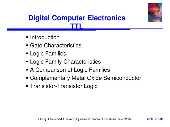
Digital Computer Electronics TTL. Introduction Gate Characteristics Logic Families Logic Family Characteristics A Comparison of Logic Families Complementary Metal Oxide Semiconductor Transistor-Transistor Logic. 25.1. Introduction.

E N D
Digital Computer ElectronicsTTL • Introduction • Gate Characteristics • Logic Families • Logic Family Characteristics • A Comparison of Logic Families • Complementary Metal Oxide Semiconductor • Transistor-Transistor Logic
25.1 Introduction • Earlier we looked at a range of digital applications based on logic gates – at that time we treated the gates as ‘black boxes’ • We will now consider the construction of such gates, and their characteristics • In this lecture we will concentrate on small- and medium-scale integration circuits containing just a handful of gates • typical gates are shown on the next slide
25.2 Gate Characteristics • The inverter or NOT gate • consider the characteristics of a simple inverting amplifier as shown below • we normally use only the linear region
We can use an inverting amplifier as a logical inverter but using only the non-linear region
we choose input values to ensure that we are always outside of the linear region – as in (a) • unlike linear amplifiers, we use circuits with a rapid transition between the non-linear regions – as in (b)
Logic levels • the voltage ranges representing ‘0’ and ‘1’ represent the logic levels of the circuit • often logic 0 is represented by a voltage close to 0 V but the allowable voltage range varies considerably • the voltage used to represent logic 1 also varies greatly. In some circuits it might be 2-4 V, while in others it might be 12-15 V • in order for one gate to work with another the logic levels must be compatible
Noise immunity • noise is present in all real systems • this adds random fluctuations to voltages representing logic levels • to cope with noise, the voltage ranges defining the logic levels are more tightly constrained at the output of a gate than at the input • thus small amounts of noise will not affect the circuit • the maximum noise voltage that can be tolerated by a circuit is termed its noise immunity,VNI
Transistors as switches • both FETs and bipolar transistors make good switches • neither form produce ideal switches and their characteristics are slightly different • both forms of device take a finite time to switch and this produces a slight delay in the operation of the gate • this is termed the propagation delay of the circuit
Rise and fall times • because the waveforms are not perfectly square we need a way of measuring switching times • we measure the rise time, tr and fall time, tf as shown below
when the input voltage to a bipolar transistor is high the transistor turns ON and the output voltage is driven down to its saturation voltage which is about 0.1 V • however, saturation of the transistor results in the storage of excess charge in the base region • this increases the time taken to turn OFF the device – an effect known as storage time • this makes the device faster to turn ON than OFF • some switching circuits increase speed by preventing the transistors from entering saturation
Timing considerations • all gates have a certain propagation delay time, tPD • this is the average of the two switching times
25.3 Logic Families • We have seen that different devices use different voltages ranges for their logic levels • They also differ in other characteristics • In order to assure correct operation when gates are interconnected they are normally produced in families • The most widely used families are: • complementary metal oxide semiconductor (CMOS) • transistor-transistor logic (TTL) • emitter-coupled logic (ECL)
TTL Characterstics • Transistor-transistor logic (TTL) • based on bipolar transistors • one of the most widely used families for small- and medium-scale devices – rarely used for VLSI • typically operated from 5V supply • typical noise immunity about 1 – 1.6 V • many forms, some optimised for speed, power, etc. • high speed versions comparable to CMOS (~ 1.5 ns) • low-power versions down to about 1 mW/gate
25.5 A Comparison of Logic Families
25.7 Transistor-Transistor Logic • Discrete TTL inverter and NAND gate circuits
Key Points • Physical gates are not ideal components • Logic gates are manufactured in a range of logic families • The ability of a gate to ignore noise is its ‘noise immunity’ • Both MOSFETs and bipolar transistors are used in gates • All logic gates exhibit a propagation delay when responding to changes in their inputs • The most widely used logic families are CMOS and TTL • CMOS is available in a range of forms offering high speed or very low power consumption • TTL logic is also produced in many versions, each optimised for a particular characteristic