Download
1 / 56
711 likes | 1.2k Views
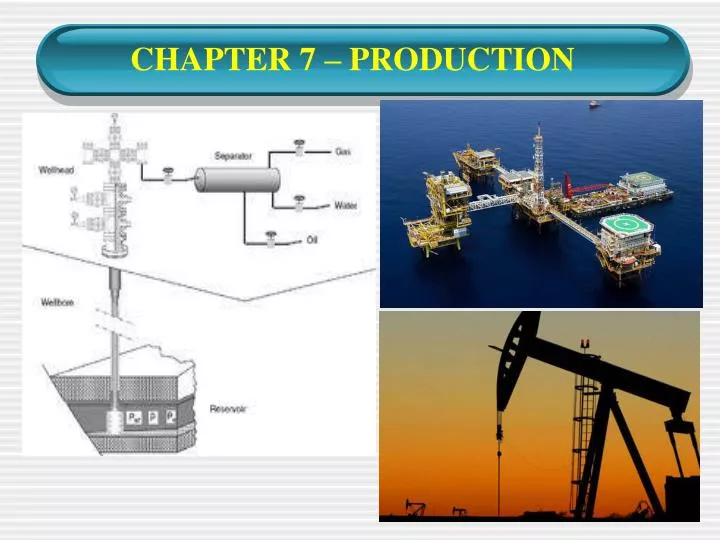
CHAPTER 7 – PRODUCTION. CONTENTS. Introduction Flowing Wells Artificial Lift Oil Treating Storage and Sale of Oil Salt Water Disposal. Introduction. The production stage is the most important stage of a well's life, when the oil and gas are produced .

E N D
CONTENTS • Introduction • Flowing Wells • Artificial Lift • Oil Treating • Storage and Sale of Oil • Salt Water Disposal
Introduction • The production stage is the most important stage of a well's life, when the oil and gas are produced. • By this time, the oil rigs used to drill and complete the well have moved off the wellbore, and the top is usually outfitted with a collection of valves called a Christmas tree or Production trees. • These valves regulate pressures, control flows, and allow access to the wellbore in case further completion work is needed. • From the outlet valve of the production tree, the flow can be connected to a distribution network of pipelines and tanks to supply the product to refineries, natural gas compressor stations, or oil export terminals.
Introduction • As long as the pressure in the reservoir remains high enough, the production tree is all that is required to produce the well. • If the pressure depletes and it is considered economically viable, an artificial lift method can be employed.
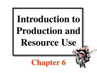
Introduction Typical Crude Oil Production Train
Flowing Wells • Defined as any well which has sufficient pressure in the reservoir to cause the oil or gas to flow naturally to the surface through the wellbore. • A well which produces oil or gas without any means of artificial lift. • They require relatively little equipment or expense to bring the oil to the surface. • The equipment commonly used consists of tubing, wellhead and x-mas tree.
Artificial Lift • Artificial lift is a technique used to bring oil from the reservoir to the surface because of decreasing reservoir pressure. • Generally this is achieved by the use of a mechanical device inside the well (known as pump or velocity string) or by decreasing the weight of the hydrostatic column by injecting gas into the liquid some distance down the well. • Artificial lift is needed in wells when there is insufficient pressure in the reservoir to lift the produced fluids to the surface. • It also often used in naturally flowing wells (which do not technically need it) to increase the flow rate above what would flow naturally.
Artificial Lift • There are currently four common methods of artificial lift: • Beam pumping • Submersible pumping • Gas lift • Hydraulic pumping
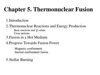
Artificial Lift - Beam Pumping • The pump is designed to be inserted inside the tubing of a well and its main purpose is to gather fluids from beneath it and lift them to the surface. • The most important components are: the barrel, valves (traveling and fixed) and the piston. • The pump is connected to the pumping unit at the surface by a string of sucker rods. • Sucker rods are stroked up and down in the tubing, activating the pump at the bottom.
Artificial Lift - Beam Pumping • At the surface, a large mechanical device called the beam pumping unit is attached.
Artificial Lift - Beam Pumping Beam Pumping Diagram
Artificial Lift - Beam Pumping • Depending on the size of the pump, it generally produces 5 to 40 litres of liquid at each stroke. Often this is an emulsion of crude oil and water. • Pump size is also determined by the depth and weight of the oil to remove, with deeper extraction requiring more power to move the heavier lengths of sucker rods. • Advantages of beam pumping: • High system efficiency. • Economical to repair and service. • Flexibility - adjust production through stroke length and speed. • High salvage value for surface unit and downhole equipment.
Artificial Lift - Beam Pumping • Advantages of beam pumping: • Limited to relatively low production volumes, less than 1,000 barrels per day. • Limited to onshore application (big surface unit required).
Artificial Lift - Submersible Pumping (ESP) • Consists of an electric motor attached to a pump on the end of the tubing string. • The electric motor turns a centrifugal pump which forces oil from the bottom of the well, up through the inside of the tubing, and out at the surface. • The electricity is suppliedthrough an electric cable attached to the side of the tubing and connected to the electric motor.
Artificial Lift - Submersible Pumping (ESP) • Advantages of ESP: • High volume and depth capacity. • High efficiency over 1,000 BPD • Low maintenance. • Minimal surface equipment requirements. • High resistance to corrosive downhole environments. • Use in deviated wells and vertical wells with doglegs. • Disdvantage of ESP: • Poor ability to pump sand.
Artificial Lift – Gas Lift • A series of devices called gas lift valves are inserted into the sides of the tubing. • The gas is injected into the well through the tubing-casing annulus and enters the tubing through the gas lift mandrels and gas lift valves. • The fluid in the tubing is made lighter by the gas, and as a result, the mixture is pushed to the surface by reservoir pressure.
Artificial Lift – Gas Lift • A source of gas, and compression equipment is required for gas lift. • Proper installation and compatibility of gas lift equipment, (surface and in the wellbore), are essential to any gas lift system. • Advantage of Gas Lift: • Gas Lift is an artificial lift process that closely resembles the natural flow process and basically operates as an enhancement or extension of that process. The only major requirement is an available and economical supply of pressurized gas.
Artificial Lift - Gas Lift • Disadvantages of Gas Lift: • Not feasible if no source of gas present. • High initial capital purchase cost • Maintenance intensive. • Difficult to operate.
Artificial Lift – Hydraulic Pumping • High pressure oil, is pumped into the well through the tubing string. • At the bottom of the well, the powered oil enters a mechanical device, causing it to reciprocate. • This mechanical device activates a pump, which lifts the oil from the producing formation, together with expended powered oil to the surface. • The systems consist of a surface power fluid system, a prime mover, a surface pump, and a downhole jet or pump.
Artificial Lift – Hydraulic Pumping • Power fluid from surface actuates the engine, which in turn drives the pump, and power fluid returns to the surface with the produced oil. • Advantages of Hydraulic Pump: • No moving parts. • High volume capability. • Multiwell production from a single package. • Low pump maintenance. • Disadvantages of Hydraulic Pump: • High initial capital cost. • Complex to operate.
Oil Treating • Generally, what comes out of the well is a mixture of oil, water, gas, and even sand. • Foreign material, such as water and sand must be separated from the oil and gas before they can be sold. • This process is known as oil treating or oil dehydration, in which water is removed from the oil. • The amount of this foreign material is referred to as the basic sediment and water (BS&W). • Normally, the BS&W content must be less than 1% before the oil will be acceptable for sale. • Basic types of equipment used for oil treating are separator, free-water knockout and heater-treater.
Separator • A separator is a large pressure vessel designed to separate production fluids into their constituent components of oil, gas and water. • Separator utilize the force of gravity to separate oil-gas mixtures (due to different densities of the fluids). • The oil which is heavier than the gas falls to the bottom of the vessel and taken off through the fluid line. • The lighter gas rises to the top and is removed for separate sale.
Separator • Major components of separator: • primary separation device and/or section. • secondary “gravity” settling (separating) section • mist extractor to remove small liquid particles from the gas. • Gas outlet • Liquid settling (separating) section to remove gas. • Lquid outlet
Classification of Separator • Classification by Operating Configuration • Horizontal separator. • may vary in size from 10 or 12 in. in diameter and 4 to 5 ft seam to seam (S to S) up to 15 to 16 ft in diameter and 60 to 70 ft S to S. • manufactured with monotube and dual-tube shell • Vertical separator. • vary in size from 10 or 12 in. in diameter and 4 to 5 ft S to S up to 10 or 12 ft in diameter and 15 to 25 ft S to S. • Spherical separator. • usually available in 24 or 30 in. up to 66 to 72 in. in diameter.
Classification of Separator • Classification by Function • Two phase separator. • gas is separated from the liquid with the gas and liquid being discharged separately. • Three phase separator. • In three-phase separators, well fluid is separated into gas, oil, and water with the three fluids being discharged separately.
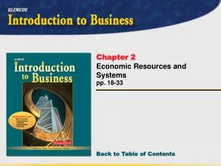
Monotube Horizontal Separator Typical Horizontal Separator
Free Water Knockout • Used to separate oil, water and gas. • These mixtures flow into the vessel through an inlet valve and then are allowed to slow down in the large settling chamber. • Any free water mixed with the oil settles to the bottom, oil is removed through a separate line and gas which rises to the top is extracted through a third line. • In principle, free-water knockout is almost identical to separator . • The vessel is called a free-water knockout because it is designed to eliminate only free water, not water which has been emulsified.
Free Water Knockout • The oil and water outlets are controlled by level controlled valves, which prevent the vessel from draining completely and keep the gas trapped in the top of the vessel. • Commonly used for low pressure wells and can be used to handle high volumes of fluid.
Heater-Treater • Also called emulsion treater, used to separate oil and water emulsions. • Similar to free-water knockout but the treater has heating capability with the inclusion of fire tubes. • The combustion of the gas within the fire tubes is used to heat oil and water emulsion.
Heater-Treater • As the oil and water mixture grows hotter, the emulsion breaks and forms into clean oil and clean water. • The water is removed from the bottom and sent to the water disposal system. • The clean oil is drawn off the center of the vessel andsent to the oil storage tanks for sale. • Any natural gas in the oil-water emulsion exits at the top of the heater-treater.
Combinations • A typical combination of equipment is shown below. • Oil, water and gas produced as a mixture sent into free-water knockout. • The remaining oil and water emulsion leaves the free-water knockout and is transferred to the heater-treater. • On an offshore platform, a high pressure separator often will be used instead of the free-water knockout. Surface facilities for typical oil well
Oil Storage and Sales - Onshore • At a typical facility, sufficient storage is provided toaccommodate oil from two to three days of production. • Oil may be withdrawn from the tank and sold bytruck/tanker or through pipeline to the refinery. • Lease Automatic Custody Transfer measures the volume of oil as it passes into the pipeline. It also measures the BS&W content.
Oil Storage and Sales - Offshore • Offshore production platforms can sometimes be equipped with oil storage equipment if the platform is located in shallow water. • The clean oil can be sold through a pipeline extending from the platform along the sea floor to the land.
Oil Storage and Sales - Offshore • In deep water operation, oil is shipped through a pipeline along the sea floor to another storage platform in shallow water. • Sometimes, storage platform in not necessary and the oil is shipped directly into the sales line. • For remote oilfield, deepwater locations and small oilfield, where seabed pipelines are not cost effective, the use of FPSO is a good option. • Oil is stored in the FPSO and will be offloaded onto tanker.
Oil Storage and Sales - Offshore Floating, Production, Storage and Offloading (FPSO)