Download
1 / 23
230 likes | 357 Views
USCMS HCAL. TriDAS Update Drew Baden University of Maryland http://www.physics.umd.edu/hep/HTR/hcal_may_2003.pdf. SBS. CLK. D C C. CAL REGIONAL TRIGGER. H T R. H T R. H T R. 16 bits @ 80 MHz. TTC. 32 bits @ 40 MHz. QIE. CCA. GOL. QIE. QIE. CCA. QIE. GOL. QIE.

E N D
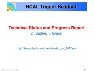
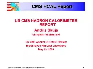
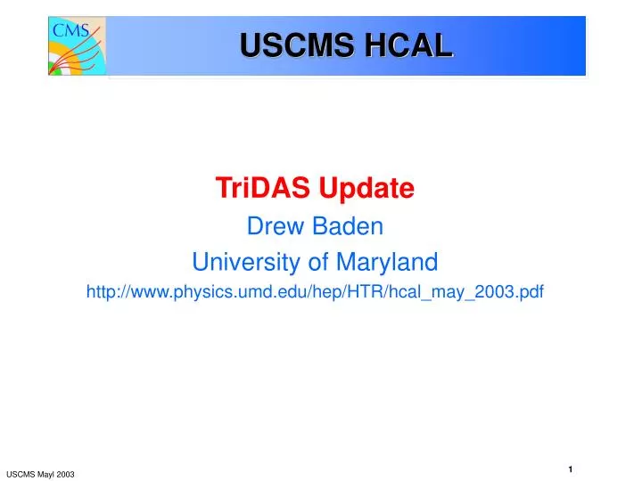
USCMS HCAL TriDAS Update Drew Baden University of Maryland http://www.physics.umd.edu/hep/HTR/hcal_may_2003.pdf
SBS CLK D C C CAL REGIONAL TRIGGER H T R H T R H T R 16 bits @ 80 MHz TTC 32 bits @ 40 MHz QIE CCA GOL QIE QIE CCA QIE GOL QIE CCA QIE FE/DAQ Electronics S-Link: 64 bits @ 25 MHz Trigger Primitives READ-OUT Crate Rack CPU 12 HTRs per Readout Crate, 2 DCC FRONT-END RBX Readout Box (On detector) HPD Shield Wall Fibers at 1.6 Gb/s 3 QIE-channels per fiber FE MODULE
DCC Logic Mezzanine Card TTCRx 3x Link Receiver Fast Timing/ Control DAQ S-LINK64 Spare Standard PMC Site (33MHz 64 bit) 235 pin 2mm Connector DCC • Production boards made • Logic boards made • Firmware shakedown • LRBs made • DCC motherboards successfully tested testbeam 2002
HTR Principal Functions 1. Receive front-end data for physics running • Synchronize optical links • Data validation and linearization • Form TPG’s and transmit to Level 1 at 40 MHz • Pipeline data, wait for Level 1 accept • Upon receiving L1A: • Zero suppress, format, transmit to the concentrator (no filtering) • Handle DAQ synchronization issues (if any) 2. Calibration processing and buffering of: • Radioactive source calibration data • Laser/LED calibration data 3. Support VME data spy monitoring • Will adhere to CMS VME64 standards
HTR Status • Rev 1 run Summer 2002 testbeam • Board worked well – all functional requirements met • Big concern on mechanical issues for production • Had a difficult experience with previous board manufacturing • Rev 2 produced March 2003 • Board production changes: • New assembler, in-house X-ray, DFM review, QC • Gold plated (Rev 1 was white-tin) for better QC • Changes to HTR: • Change from Virtex 1000E FBGA (1.00mm) to Virtex2 3000 BGA (1.27mm) • Added stiffeners • Moved all SLB/TPG output to front-panel daughterboards • Modified Rx refclk scheme (the usual TTC/refclk clocking concerns) • Full 48 channel capability (Rev 1 was “half HTR”) • As of this date, no issues – this board is functionally a success
HTR Rev 3 • No more design changes – this is the final HTR • 30 boards delivered April 21 • As of Friday (May 2) 12 have gone through final checkout • All systems except connectivity to SLB • Fiber links checked out at 1.7Gbaud bit rate (1.6Gbaud is CMS requirement) • Frame clock up to 2.0Gbaud bit rate and it stays synchronized • No BER yet…will do a lab measurement soon • 12 boards x 16 links ~200 links(~5% of total) with no problems • Minor adjustments will be needed for front panels, stiffeners, etc. • Will battle test these boards this year • Testbeam to begin this month • Vertical Slice tests after summer
16 Dual-LC O-to-E VME Stiffeners TTC mezzanine Deserializers 6 SLBs Xilinx HTR Rev 3 (cont)
HCAL Clocking • DCC – no difficult synchronization issues here • For HTR, need 2 different kinds of clocks: 1. Synchronized LHC clock for Xilinx system clock and SLBs • Maintain phase synchronization with entire CMS pipeline • Allow SLBs to do their job • Frequency jitter requirement not critical 2. Precise 2xLHC clock for Deserializer refclk ONLY • 30-40ps pkpk jitter spec • Used ONLY for deserializers • Phase synchronicity with LHC clock not important • Princeton fanout board will receive TTC, clean up clocks with QPLL, fanout signals
FPGA TTCrx QPLL Clock Distribution TTC fiber O/E TTCrx TTC TTC TTC Brdcst<7:0>, BrcstStr, L1A TTC .. .. .. .. .. .. .. .. BC0 BC0 distribution to 6 SLBs and to 2 Xilinx Cat6E or Cat7 Cable (very low X-talk) CLK40 CLK40 CLK80 CLK80 Princeton Clock/TTC Fanout Board to Ref_CLK of SERDES (TLK2501) Test Points for RxCLK and RxBC0 80.0789 MHz .. .. HTR
TTC receiver - TTCumd • General purpose TTC receiver board (TTCumd) • TTCrx ASIC and associated • PMC connectors • Will be used to receive TTC signal by HTR, DCC, and clock fanout boards • No signal receivers! • Copper/fiber receivers must be on the motherboard • Signal driven through TTC connectors • Tested successfully by Maryland, Princeton, BU groups
HTR Integration Goals 2003 • Continued development of HTR firmware • Commission TPG path • Firmware, LUTs, synchronization, SLB output… • Monitoring, error reporting, etc. (information sent to DCC) • Testbeam May 2003 • Support calibration effort and continue commissioning the system • Run synchronously in May • Vertical slice tests, Fall 03 • Fully pipelined, monitoring, TPG, DAQ, synchronization, clocking…. • Develop software to support DAQ activities • Testbeam software improvements • Princeton group built testbeam DAQ • Software for commissioning • Allow us to verify fiber mapping • Download LUTs, firmware version, etc.
HCAL TPG • Under development… • Preliminary FPGA code for TPGs done • LUT for linearization (downloadable), 0.5GeV steps, 255Gev max ET • E to ET and sums over as many as 7 channels • Not implemented in code yet…TBD • Muon window in E • BCID filter algorithm TBD from testbeams • Compression LUTs for output to SLBs • Utilization is ~50% of Virtex2 3000 • We are confident this chip will be sufficient • Simulation effort under way… • Latency issue • See below – we are working on this…
HTR Production • Full contingent of HTRs: 260 boards • Includes 10% spares, 20% spares for parts • Full production will begin after: • Testbeam demonstrates I/O works under battle conditions • Successful testing of the 6 SLB daughter card functions • Understanding of how to meet latency issues • We are still some clock ticks short, but firmware is still very immature for the TPG part of the HTR (see slides below) • If all goes well…sometime this summer or fall • There is no reason to hurry other than to finish with the R&D part of the project • We are confident that the current board design will be final
Overall Commissioning Schedule • Summer 2003 testbeam • Repeat previous test w/production prototype boards • Fall 2003 Slice tests • HCAL will join as schedule allows • 2003/2004 HCAL burn-in • Continue with firmware development/integration as needed • 2004/2005 Vertical Slice and magnet test • We will be ready • All HCAL TriDas production cards involved • October 05 beneficial occupancy of USC • Installation of all racks, crates, and cards • We do not anticipate any hardware integration • Should be all firmware / timing / troubleshooting
TI TI TI FPGA Xilinx XC2V LC LC TI LC TI LC TI TI TI ESR Review Item 1 “Use of an obsolete TI component for the data link receiver” • Misconception on the part of the committee • TI TLK2501 is NOT obsolete. • This is a Gigabit ethernet transceiver. • There is no reason to believe TI will stop making these parts. • If they do, someone will make something else compatible. • Stratos receivers are also NOT obsolete. • Dual receivers are out of favor, Transceivers are in favor • What is obsolete is our $99/part. If we need more, they will charge $133/part (or more)
ESR Review Item 2 “The random latency problem that comes with using the 8bit/10bit link protocol” • The “random latency” has to do with the TI Serdes function • Two clocks here: incoming data clock and reference clock • Serdes part has an internal asynchronous FIFO to implement 8B/10B protocol • But this is NOT the fault of the protocol! • Any protocol which includes a clock, to be recovered, will have this. • TI does have a 2-3 clock tick random latency with 50% probability for 2 or 3 • We can use VME controllable reset and comparison to achieve the 2 clock tick lesser latency • Can readout SLBs and use relative latency to correct pointers • Can use FE BC0 signals
ESR Review Item 3 “Routing of large no. of stiff cables to the front of the HTRs versus other configurations such as a transition module” • Transition module is NOT POSSIBLE. Forget about this. • Would cost us 6 months at least (time and engineering $) • Strain relief: • Each HCAL rack will have 2 VME 9U crates • Each 9U crate will have an accompanying 6U strain relief panel • Changing to 15m quad cables (from 20m 2xdual “Wesley” cables) will greatly reduce torques on SLB cards • We will test these cables this summer – need Wisconsin Vitesse test setup • Each SLB card will be attached to the HTR front panel, and screwed into HTR motherboard • We believe this will work fine.
ESR Review Item 4 “Ensuring appropriate quality assurance and testing at the HTR board fabrication facility” • We agree, this is a big worry. • Have used new high-tech assembler for Rev 3 (pre-production) • Note: almost any assembler will have startup issues • Overall techniques are more important than QA, which comes after the fact • We have chosen an assembler with very modern (and expensive) equipment. • An engineering review by the assembler is included in the assembly cost • Our biggest problem was fine-line BGA (1.0 mm pitch) implementation • Current version uses standard 1.27mm pitch BGA • Given current experience, we believe we have solved this…
ESR Review Item 5 “Providing sufficient FPGA excess capability against possible future enhancements to the firmware” • HTR FPGA change: Virtex/1000E to Virtex2/3000 • Current firmware uses • 83% of all RAM resources • FIFOs, LUTs, etc. this will not change • 50% of all Logic resources • Room for more logic • Room for more memory (can use distributed memory) • The sky is not the limit, but we think we’re ok here • Firmware has evolved quite far thanks to Tullio Grassi’s efforts
ESR Review Item 6 “Minimizing the trigger latency” • Current total 50 – 57 clocks • Very rough guesses • Many numbers have not been measured • Optimizations: • Fiber cables need to be 90m? • HTR firmware needs optimization • Deserializer random latency fix • TPG cables changed to 15m will save 1 tick • Others…main efforts over next 6 months
TP_Bypass 1 0 8 9 TPG Path L1 Filter Sum in ET INPUT LUT Lineariz. and Et ETcomp Compression LUT TP Sum Consecutive Time-samples ET[9:0] QIE-data 10 10 7 10 Muon LUT Peak Detection Muon bit 2 1 Mask & Reset “NO-SHOWER” LUT take care of cases where showers can leak into a cell and incorrectly set the muon bit. BCID Delay to synchronize with BCID 2 2 2 2 BCID avoids to flag as a muon the tail of a more energetic event
Other ESR Concerns • Reliability/maintenance • Replacement of HTRs not an issue – HTRs not in hi-rad region • Data link error detection • Not difficult to implement, just requires coordination. • Under consideration, schemes are evolving, dealing with e.g. • Loss of synch • Trigger acceptance violations • Buffer overflow (actual and warnings so DCC can cause L1 to throttle) • Use of BC0 from front end • Inline pedestal determination • Zero suppression • DAQ format