Download

1 / 49
530 likes | 745 Views
Rainfall Excess Method. For Deranged Networks With Depressions Harry Downing SWFWMD July 19, 2007. Surface Runoff Networks. Current Method of Rainfall Excess Determination. NRCS Method TR-55 And National Engineering Handbook-4 Curve Number Method. Soils Hydrologic Group. Land Cover.

E N D
Rainfall Excess Method For Deranged Networks With Depressions Harry Downing SWFWMD July 19, 2007
Current Method of Rainfall Excess Determination NRCS Method TR-55 And National Engineering Handbook-4 Curve Number Method
Soils Hydrologic Group Land Cover Table Catchments' CN - DCIA Soil and Land Cover Overlay with Table LU
CN Formula • S=1000/CN – 10 • Q=(P-Ia)2/(P-Ia+S); • S = maximum potential retention • P = the cumulated storm rainfall depth • Ia = initial abstraction, where Ia = 0.2*S
Definition of Hydrologic Soil Groupings • Group A – Low runoff potential when thoroughly wet, 90% or greater sand or gravel and less than 10% clays, saturated hydraulic conductivities for all soil layers exceed 5.67 inches/hour, depth to impermeable layer greater than 20 inches, and depth to water table greater than 24 inches from surface. • Group B – Moderately low runoff; 10-20% clays can have 50-90 percent sands, with loamy sand or sandy loam textures; saturated hydraulic conductivities range between 1.42 and 5.67 inches/hour; depth to impermeable layer greater than 20 inches, and depth to water table greater than 24 inches from surface. • Group C – Moderately high runoff potential, 20-40% clays with less than 50 percent sands with loam and silt loams, saturated hydraulic conductivities range between 0.14 and 1.42 inches/hour, depth to impermeable layer greater than 20 inches, and depth to water table greater than 24-inches. • Group D – High runoff potential, have greater than 40% clays and less than 50% sands, depth to impermeable layer less than 20 inches, and water table within 24 inches of the surface. Higher organic content.
Need for Alternative Method • Florida watersheds were not considered in the analysis that produced the CN array. • The SCS methodology excludes time as a variable, and therefore rainfall intensity. • Limited comparisons elsewhere have suggested significant departures between handbook and data-defined CNs. In addition, the primary reference for the CN method, NEH-4 suggest that the soils-based table values are but guides, and that local values should be used if possible. • The CN procedure does not work well in karst topography areas. This is because a large portion of the flow is subsurface rather than direct runoff. • Typically runoff generated from CN procedures do not match rainfall-runoff data for local watersheds, and the 0.2S for initial abstraction (Ia) was not corroborated by linear regression techniques.
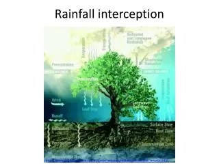
Types of Rainfall Excess • Infiltration excess overland flow-This occurs when the rate of rainfall on a surface exceeds the rate at which water can infiltratethe ground, and any depression storage has already been filled. This is called infiltration excess overland flow, Hortonian overland flow (after Robert E. Horton), or unsaturated overland flow. • Saturation excess overland flow-When the soil is saturated and the depression storage filled, and rain continues to fall, the rainfall will immediately produce surface runoff. The level of antecedent soil moisture is one factor affecting the time until soil becomes saturated. This runoff is saturation excess overland flow or saturated overland flow (after Thomas R. Dunne). • Subsurface return flow-After water infiltrates the soil on an up-slope portion of a hill, the water may flow laterally through the soil, and exfiltrate (flow out of the soil) closer to a channel. This is called subsurface return flow or interflow.
Characterization Soil Infiltration and Runoff Excess • Infiltration is a function: • Soil Suction (ψ) = attraction of water to soil particles through electrostatic forces between the polar bonds of water and the particle surfaces • Gravity (z) • Soil Hydraulic Conductivity (K) • One-Dimensional Richard’s Equation: • ∂θ/∂t = ∂/∂z (K dΨ/dθ ∂θ/∂z + K) • Horton’s Equation: f(t) = fc + (f 0 - f c) e –kt • Green and Ampt Method: • f(t) = K(Ψ∆θ / F(t) + 1); infiltration rate • F(t) = Kt + Ψ∆θ ln (1+F(t)/ Ψ∆θ ); amount infiltrated - solved by successive substitution, etc.
Advantages of the Green-Ampt Method • Parameters Based Upon Published Soil Properties Provided by the NRCS and IFAS • Allows Direct Comparison of Rainfall Intensities to Soil Infiltration Capacity on a Real Time Basis • Allows Comparison of Cumulative Rainfall Infiltrated to Estimated Soil Storage Above Water Table • Applies to Most Soil Types and Conditions (Multi-Layer)
Soil Parameters • NRCS - ‘Soil Survey’ and Soil Survey Geographical (SSURGO) Database • IFAS - ‘Site Specific Soil Characterization’ • Site Specific Characteristics from ERP Applications • Table Information from Other Studies (Text Books)
Soil Moisture Curve for Each Horizon (Gravity Water) Land Surface Each Horizon Depth Above Water Table Water Table Moisture Content Percent
Soil Moisture for 200 cm Depth to WT Soil Moisture Saturation / Soil Porosity Height Above Water Table Centimeters Soil Moisture Content %
Soil Storage vs. Depth to WT Soil Storage in Inches Depth to WT Feet
Proposed Procedure • Soil Parameterization (Green–Ampt) • Spatial extent (GIS) • Depth to water table • Soil Storage • Soil Hydraulic Conductivity • Soil Suction
Proposed Procedure (Cont’d) • Land Cover Parameterization • Residential • Commercial • Industrial • Transportation • Agriculture (Citrus, Row Crops, Irrigation Method, Timing) • Natural - Uplands and Wetlands * Impervious Area, DCIA
Proposed Procedure (Cont’d) • Catchments • Delineation – Deranged Networks (Arc Hydro Tools) • Union of Soil and Land Cover Information • Identification of Percolation Areas (Depression and/or SMAs) • Determine Initial Conditions (Water Table, Ponds, and Depressions) * - (Historical Data, Biological Indicators, Structure Information)
Proposed Procedure (Cont’d) • Rainfall Excess Hydrograph • For Each Unique Polygonal Area of Catchment • Use Design Storms for Area • Verification Storm Analysis • Determine runoff (Green-Ampt and DCIA) • Develop Composite Rainfall Excess Hydrographs by summing the individual polygons hydrographs
Proposed Procedure (Cont’d) • Percolation at DepressionsHydrograph • Identification of Expected Ponding Area for Initial Try • Rainfall Excess will be 100% over area - infiltration • Geotechnical Testing or Retrieval of ERP Data to Determine Infiltration/Percolation Parameters (bulk densities, porosities, KV, KH, and expected WT Conditions) • Develop initial inflow hydrographs • Perform Mounding Analysis • Remodel