Download
1 / 35
350 likes | 478 Views
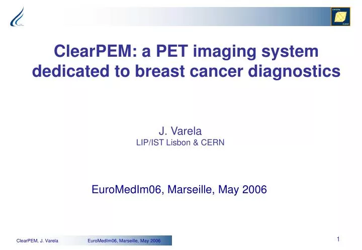
ClearPEM: a PET imaging system dedicated to breast cancer diagnostics. J. Varela LIP/IST Lisbon & CERN. EuroMedIm06, Marseille, May 2006. Sensitivity@350 keV (%). 4 cm off-axis. 3 cm off-axis. Y-axis (cm). 2 cm off-axis. 1 cm off-axis. central slice. X-axis (cm). ClearPEM Project.

E N D
ClearPEM: a PET imaging system dedicated to breast cancer diagnostics J. Varela LIP/IST Lisbon & CERN EuroMedIm06, Marseille, May 2006
Sensitivity@350 keV (%) 4 cm off-axis 3 cm off-axis Y-axis (cm) 2 cm off-axis 1 cm off-axis central slice X-axis (cm) ClearPEM Project The ClearPEM scanner is developed in the framework of the Crystal Clear Collaboration at CERN • Consortium PET-Mammography, Portugal TAGUSPARK – Parque de Ciência e Tecnologia LIP - Laboratório de Instrumentação e Partículas Hospital Garcia Orta - Serviço Medicina Nuclear IBEB - Instituto Biofisica e Engenharia Biomédica IBILI - Instituto Biomédico de Investigação da Luz e Imagem INESC - Instituto de Engenharia de Sistemas e Computadores INEGI - Instituto de Engenharia Mecânica e Gestão Industrial • CERN, Geneva • VUB, Brussels
ClearPEM Requirements • Good spatial resolution ( 2 mm, whole FoV) • Fine crystal segmentation (2x2 mm) • DoI measurement with adequate resolution (FWHM ~2 mm) • High Sensitivity ( 0.05 cps/Bq, center FoV) • Solid angle coverage as large as possible • High photon interaction probability (20 mm long crystals) • High efficiency to Compton events in the detector (> 75%) • Minimize dead time in data acquisition (<10 % at highest rate) • Low Random Background ( <25%, close to the chest) • Good time resolution (~ 1 ns)
ClearPEM Imaging System Breast and axilla exams • Breast exams with the patient in prone position • The plates rotate around the breast • PEM plates can be rotated for axilla exams PEM Detector Plates PEM Robotic Device
ClearPEM Detector • ClearPEM Detector: • Two detection plates • 192 crystal matrices (8x4 crystals each) • Front-back APD readout for DoI measurement • 6300 LYSO:Ce crystals • Avalanche photodiodes • Low noise electronics Plate surface 14x16 cm2 Optical simulation ClearPEM detector model
2x2x20mm depolished Light Yield Energy resolution Crystals Quality Control • Production of 6300 crystal pixels concluded • Measurements with miniACOS (CERN): • 700 crystals measured • Light yield dispersion (~12% rms) miniACOS LYSO:Ce Crystals 2 x 2 x 20 mm3
Relative gain of APD Pixels = 4.6% S8550-01 APD arrays Quality Control of APD Arrays 400 APD-arrays S8550-01 (Hamamatsu) • Quality Control: • Bias voltage for M=50, 100, 200 • Id/M per subarray • dM/dV (%/V) • Relative gain of individual pixels Dark Current (Id) Gain variation per Volt dM/dV<4%/V Id (16 pixels) < 70 nA APD Number
LYSO/BaSO4 Matrix Performance of Detector Modules • Quality Control: • Gain uniformity • Energy resolution • DoI resolution • Cross-talk Measurements of 24 Detector Modules See also poster P3_212 “Long-term stability of Clear-PEM Detector Modules”, C. Ortigão et al.
Gain Uniformity & Energy Resolution • Flood irradiation Cs-137 • Measurement of relative gain of Detector Module pixels • Energy resolution at 662 keV • Results for 24 Detector Modules Relative Pixel Gain Energy Resolution RMS= 12.9% Average = 13.4%
Depth of Interaction + 7 mm Bottom Top Crystal Each asymmetry peak corresponds to irradiation at one beam location Collimated beam DoI Resolution for 32 pixels of one Detector Module FWHM ~ 2 mm A=(T-B)/(T+B)
Top-Bottom Asymmetry • Flood irradiation Cs-137 • Measurement of the width of the asymmetry distribution Quality Control of 24 Modules Asymmetry A=(T-B)/(T+B)
Average cross-talk per Module Cross-Talk Method: Select photopeak events in one crystal and study energy deposit in neighbor crystals Na22 “flood” Red – select 511 keV Green – select 1274 keV Average crosstalk: 2 - 3 % 24 modules measured 1056 walls
Time Resolution Non-optimized electronics (peaking time ~150 ns) Sampling ADC 10 bits 100 MHz Time difference APD(top) – APD (bottom) Single photon time resolution 2.1 ns (RMS) Preliminary
Full System Simulation ClearPEM Simulation Framework • Monte – Carlo Simulations using GEANT4 • NCAT phantom • Standardized uptake values one hour after the injection of 370 MBq. • Concentration of 2.1 kBq/cc for the soft tissue. • Detailed detector geometry • Includes trigger and data acquisition simulation
Counting Rates A B C Single rate per Detector Head ~ 2.2 MHz (E>50 keV) Fraction of Random Coincidences < 30% Standard uptakes for FDG injection of 370 MBq; Breast uptake 2.1 KBq/mL
DAQ/Trigger Performance DAQ and Trigger Efficiency: - above 90% for E>200 keV Time Resolution - single photon rms ~1.5 ns - photostatistics contributes ~1 ns - electronic noise ~1000 e-
Coronal view Transverse view Sagittal view Monte Carlo Sensitivity Image “Full simulation” sensitivity image (uniform activity in the FoV) Coronal view sequence Sensitivity pattern: irregular variation Packing fraction: 52% FOV dimension: 16.2 x 14.5 cm2
Reconstruction Performance Using Monte Carlo Simulated Data Chain Phantom NCAT Breast Phantom Scanner rotation axis Scanner rotation axis Performance evaluation in optimal imaging conditions Performance evaluation in realistic imaging conditions Detector Plates in 2 orthogonal orientations
Point Source Reconstruction • Chain phantom • 10 mm between point sources; • No background activity.
lesion : background activity concentration lesion : background activity concentration lesion : background activity concentration lesion : background activity concentration 1:13 1:13 1:13 1:13 1:10 1:10 1:10 1:10 1:5 1:5 1:5 1:5 1:4 1:4 1:4 1:4 Good visibillity Poor visibillity Not visible Lesion Reconstructed Images 10 mm Ø lesion 7 mm Ø lesion 5 mm Ø lesion 3 mm Ø lesion (5 min total acquisition)
Data Acquisition Requirements • Coincidence digital trigger: • Digital algorithms (time and energy) • Time resolution ~ 1 ns • Good efficiency for multi-hit (Compton) events • Fast Data Acquisition: • Data acquisition system able to cope with a single photon background rate of the order of 10 MHz • The data acquisition efficiency larger than 90%. • Pipeline structures for minimum dead time
On-Detector Off-Detector Frontend Boards DAE crate Digital trigger Data reduction Data readout 600 MHz PC Ampli AnalogMux 192:2 ADC 100 MHz 10 bit Serializer Service Boards Architecture of Electronics Systems Frontend Boards Data Acquisition Electronics • Amplifier/ Multiplexer ASIC: • Sampling ADC (100 MHz) • Links LVDS • Crate 6U • 4 DAQ boards • 1 Trigger/DCC board • FPGAs 4 M gates Service Boards • APD Bias Voltage regulation • T, P monitoring • Power distribution
Frontend ASIC Frontend ASIC Specifications: Technology AMS 0.35 m CMOS Input: 192 channels Noise: ENC ~ 1000 e- Power per chip : < 2 mW/channel Clock frequency : 100 MHz Shaping: Peaking time 40 ns Analog memories: 10 samples Output multiplexing: 2 highest channels ASIC V1 Layout • ASIC V1: • sampled-data memory, multiplexers, control logic OK • input amplifier with unstable bias levels
Layout of Test ASIC V2 8 channels + switches + control logic + self-test Area – 9.44 mm2 multiplexers + buffers 1600 m 5900 m Control Logic 4 channels 4channels
DAQ CONN C D FE Serv LV A A D C F A A V O O E H S C C D S A A v L I I O O r e V S S S S V A A A A e r I I L v O O A A D S C C S H E O O V F A A C D A A FE Serv LV D C DAQ CONN Frontend Electronics Integration • Compact system inside the PEM Detector Head: • 6000 APD channels • 400 HV lines • 160 high speed (600 MHz) output lines • High frequency clock (100 MHz) Frontend Board Detector Supermodule
Data Acquisition System DAQ module: - pipeline data storage - hit energy and time calculation Trigger module: - performs coincidence trigger - random triggers - singles trigger Filter Module: - rejects out-of-time data - rejects high multiplicity events DCC module: - collects relevant data - data transfer to PC
Control PCI Interface Processing Trigger and Data Acquisition Boards DAQ Board DAQ Board tested successfully Processing Deserializers TRG/DCC Board is under test TRG/DCC Board Control
Detector Heads Detector heads Patch Panel Water distribution block Adapter for source mounting Collision detection switches Cable carrier Electromechanical safety switch
PrototypeUnderAssembly Robotic Device Movements
Conclusions The ClearPEM mammography scanner promises to have an interesting performance. Work is under way to conclude the prototype and to prove these expectations this year. Clinical tests are foreseen in 2007
ClearPEM Sensitivity Along axis parallel to plates Results with full simulation: Sensitivity at FOV center = 0.06 cps/Bq Along axis perpendicular to plates Plate separation 10 cm
Effect of Randoms to PEM Images Investigate impact of random coincidences from outside the FOV in the quality of PEM images = + Simulation approach Random coincidence background (event generator) Example: True coincidence background (Geant4 full simulation) • 5 mm Ø at 6 cm from CFOV • Lesion uptake: 20.4 kBq/ml • Breast uptake: 2.1 kBq/ml • 2 orthogonal projections • 300 s acquisition • 3D-OSEM reconstruction Events are mixed in the LMF file before image reconstruction + = 18% less contrast Torso region
Mechanical System Breast configuration Axilla configuration