Download
1 / 63
630 likes | 748 Views
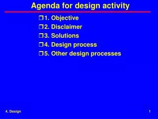
Agenda for design activity. 1. Flow diagrams 2. Instrumentation 3. State tables 4. Decision tables 5. Homework. 1. Flow diagrams. Definition Automated techniques Flowing down interfaces. 1. Flow diagrams. Definition (1 of 2).

E N D
Agenda for design activity 1. Flow diagrams 2. Instrumentation 3. State tables 4. Decision tables 5. Homework
1. Flow diagrams • Definition • Automated techniques • Flowing down interfaces 1. Flow diagrams
Definition (1 of 2) • Flow diagrams show the flow of physical quantities, data, and control into, out of, and through a product. Examples are • Power • Cooling air • Signals • Control 1. Flow diagrams
Definition (1 of 2) • Diagrams can be functional or physical • Controlling the flow is one of the strongest influences a product engineer has on the development of a product 1. Flow diagrams
Automated techniques • Excel spreadsheet • Data bases; e.g. TeamWork 1. Flow diagrams
Flowing down interfaces Product requirements concept; e.g.,power control Product design requirements requirements requirements Lower product A requirements Lower product B requirements Interface requirements requirements Product requirements suggest a concept. Design develops this concept and creates requirements for lower products and I/Fs. The I/F requirements become lower requirements 1. Flow diagrams
2. Instrumentation • Need for instrumentation • Examples of instrumentation • Value of embedding instrumentation • Costs of instrumentation 2. Instrumentation
Need for instrumentation • Build and verify activities benefit from instrumentation • Customers are wary about depending upon the results of simulation • Customers feel more comfortable with measured data 2. Instrumentation
Examples of instrumentation • Time tagging • Throughput • Trouble shooting • Access to unavailable features 2. Instrumentation
Value of embedding instrumentation • Less expensive than adding later • Common to leave in the system 2. Instrumentation
Costs of instrumentation • Expensive to collect all variables produced by the system and then figure out what to do with the data later • Expensive without stated objective • Data reduction expensive 2. Instrumentation
3. State diagrams • Example 1 • Logical control requirements in words • Complete state diagram • Simplified state diagram • Number of paths in state diagram • Truth table 3. State diagrams
Example 1 Remote terminal (RT) 1 Master bus communications self test loading operation RT 1 power switch closed open power Goal -- turn on power. Establish communications, load, and operate 3. State dagrams
Logical control requirements in words • Two power control states • 1. Off • 2. On • Off when power switch is open. • On when power switch is closed 3. State dagrams
Complete state diagram Power-state state diagram RT 1 power switch open 1 off transition paths RT 1 power switch closed RT 1 power switch open same- state transition paths RT 1 power switch closed 2 on Power-state state diagram showing state transition paths and same-state transition paths 3. State diagrams
Simplified state diagram Power-state state diagram 1 off Power switch closed Power switch open 2 on Power-state state diagram showing only state transition paths and not showing the same-state transition paths. This form is used often. 3. State diagrams
Number of paths in a state diagram • Maximum number of state transition paths is n2 • Maximum number of same-state transition paths is n • Maximum number of state transition paths excluding the same-state transition paths is n2 - n. • Maximum number doesn’t need to be present 3. State diagrams
Truth table criterion RT 1 power switch RT 1 power state open off closed on decisions A truth table has the same information as a state diagram, but it is less graphic 3. State diagrams
4. Decision tables (1 of 2) • Using decision tables • Defining number of decisions • Defining the number of paths • Defining the number of options per path • Example 1 • Creating a decision table • Defining number of decision tables 4. Decision tables
Decision tables (2 of 2) • Using canonical format • Ordering criteria rows • Adding results rows • Ordering decision columns • Checking correctness • Example 2 • Example 3 4. Decision tables
Using decision tables (1 of 3) RT 1 power-state decision table A decision table is a truth table with the information rearranged to be more compact when typed 4. Decision tables
Using decision tables (2 of 3) • Identifies all possibilities • Uncovers hidden paths • Promotes consistency • Provides concise documentation • Allows numerical checks for quality 4. Decision tables
Using decision tables (3 of 3) • Decision tables don’t guarantee that the decisions are right 4. Decision tables
Defining number of decisions (1 of 2) • Number of decisions equals the product of the number of choices for each criterion. • Must account for all the decisions • A “-” in a decision table means that the decision table doesn’t care what the value of a criterion is. 4. Decision tables
Defining number of decisions (2 of 2) RT 1 power-state Number of decisions per criterion Number of decisions It’s not necessary to show the number of decisions, but showing the number of decisions helps check the quality of the table 4. Decision tables
Defining the number of paths RT 1 power-state Add current state even though not needed in example Show the matrix of paths It’s not necessary to show the number of paths, but showing the number of paths helps check the quality of the state diagram. 4. Decision tables
Defining the number of options 1 2 14 14 2 3 3 2 2 1 matrix of options for each path (cell) total = 54 Matrix of options shows the number of options for each path. Each cell position represents a path 4. Decision tables
Example 1 (1 of 3) • Two communications states • 1. Not established (not est) • 2. Established (est) • Not established if power state is off or ability to communicate is false • Established if power state is on and ability to communicate is true 4. Decision tables
Example 1 (2 of 3) communications not established power state = on and ability to communicate = true power state = off or ability to communicate = false communications established 4. Decision tables
Example 1 (3 of 3) Communications state 4. Decision tables
Creating a decision table • 1. Use Excel • 2. Use ‘- to enter a minus into a cell • 3. Use calculating capabilities to check numbers • 4. Use non-proportional fonts • 5. Use single character criteria 4. Decision tables
Defining number of decision tables • Use one state diagram for each decision or concept • Use one decision table for each diagram • Use adjectives to avoid ambiguity 4. Decision tables
Using canonical format Example canonical format 4. Decision tables
Ordering criteria rows (1 of 3) • Listed vertically • Based on the author’s guess at the impact of each criterion on state • Strongest criterion at the top • Weakest at the bottom 4. Decision tables
Ordering criteria rows (2 of 3) • Order of the rows can be changed • Number of columns may change • Number of decisions and the path matrix remain the same • Confirms accuracy of rearranging rows 4. Decision tables
Ordering criteria rows (3 of 3) • Changing rows doesn’t leave table in canonical format • Row-order resulting in fewest number columns is not always obvious • Obtained by trial and error 4. Decision tables
Adding results rows Results in addition to state can be shown. However additional information may prevent merging some columns. 4. Decision tables
Ordering decision columns (1 of 6) • 1. Listed from left to right • 2. Weakest criterion change fastest • 3. Strongest change slowest 4. Decision tables
Ordering decision columns (2 of 6) Example canonical format 4. Decision tables
Ordering decision columns (3 of 6) • 1. Find columns in which criteria have no effect • 2. Merge such columns into a single column • 3. Replace the values of the criteria that have no effect with a “-” 4. Decision tables
Ordering decision columns (4 of 6) • The columns must be mutually exclusive 4. Decision tables
Ordering decision columns (5 of 6) Left hand Right hand Columns 1 and 2 in the left hand table are not mutually exclusive. Columns 1 and 3 in right hand table are not mutually exclusive. Results are conflicting. 4. Decision tables
Ordering decision columns (6 of 6) • Not necessary to simplify • Minimizing makes printing the decision table easier and helps definition and implementation 4. Decision tables
Checking correctness • 1. Identify all states • 2. Identify all criteria • 3. Identify all values of each criterion • 4. Enter the criteria values into the table in canonical format • Guidelines for Creating a DT (2 of 2) • 5. Determine state corresponding to each column • 6. Simplify the decision table • 7. Confirm the number of decisions 4. Decision tables
Example 2 (1 of 5) • Three load states • 1. Not loaded or loading • 2. Loading • 3. Loaded • Determined by • Communications state (not est, est -- [F,T]) • Load state (1, 2, 3 -- [1, 2,3]) • Load command (none, stop, load -- [N, S, L]) • Load status (none, failure, complete -- [N, F, C]) 4. Decision tables
Example 2 (2 of 5) • If (1) the comm state is not established or (2) the load status is failure, then the load state is not-loaded-or-loading • If (1) the comm state is established and (2) the load status is not failure and (3) the load command is stop, then the load state is loading • If (1) the comm state is established and (2) the load status is complete and (3) the load command is none and (4) the current load state is loading, then the load state is loaded 4. Decision tables
Example 2 (3 of 5) not loaded or loading (1) comm state = not est or load status = failure comm state = not est or load status = failure comm state = est & load cmnd= load & load status = not failure comm state = est & load status =complete loading (2) loaded (3) comm state = est & load cmnd= load & load status = not failure 4. Decision tables
Example 2 (4 of 5) 4. Decision tables
Example 2 (5 of 5) Problems with developing decision table ad hoc 67>54 4. Decision tables
Example 3 (1 of 4) • Two operate states • 1. Not operating • 2. Operating • Determined by • Operate command (stop, operate -- [S,O]) • Operate state (1, 2-- [1,2]) • Load state (not loaded, loading, loaded [1,2,3] 4. Decision tables