Download
1 / 29
330 likes | 707 Views
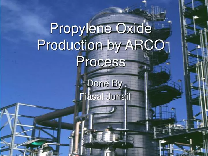
Propylene Oxide Production by ARCO Process. Done By Fiasal Juhail. Out Line:. Distillation column Reactor Pump Separator. 1.Distillation ColumnT-(100): Objective : To separate TBA from TBHP to fed it to the second reactor. Assumptions 1-Tray spacing= 0.6 m

E N D
Propylene Oxide Production by ARCO Process Done By Fiasal Juhail
Out Line: • Distillation column • Reactor • Pump • Separator
1.Distillation ColumnT-(100): • Objective : • To separate TBA from TBHP to fed it to the second reactor.
Assumptions • 1-Tray spacing= 0.6 m • 2-Percent of flooding at maximum flow rate=85% • 3- Percent of downcomer area of total area=12% • 4- The hole area =10% the active area. • 5-weir height=50 mm • 6-Hole diameter=5 mm • 7-Plate thickness=5 mm
Design Procedure 1. Collect the system physical properties. 2. Calculate liquid - vapor flow factor. = vapor mass flow rate, Kg/s = liquid mass flow rate, Kg/s = vapor density, Kg/m3 = liquid density, Kg/m3
3-Select trial plate spacing from 0.15m to 1m. 4. Calculate the net area required. = volumetric flow rate, m3/s = flooding at maximum flow rate, m/s
5. Calculate total column cross sectional area. 6. Calculate the column diameter.
7. Calculate number of holes. Where = cross sectional area of downcomer , m2 Where = net area, m2
Where = active area, m2 Where Area of one hole = = hole area, m2 Number of holes = Ah / area of one hole
8. Calculate height of the column. 9. Calculate thickness of the column. Where = column thickness, in = maximum pressure, psi = column radius, in = stress of metal, psi S = joint efficiency
10. Select the material of construction. 11. Select the material of insulation. 12. Estimate the cost of the equipment.
Centrifugal Pump Centrifugal pumps are essentially a type of enclosed pump in which a liquid is drawn in and delivered in a continuous stream by the rotation of a fan.
Assume: ή = 75% • The head of the pump (H) = Where: • H= the static head of the pump in m. • ρ= the density of the fluid kg/m3 • Break horse power (BHP) • Where, • BHP =is the break horsepower of the pump in watt • Q= flow rate in m3/s • H= the static head of the pump in m. • ρ= the density of the fluid kg/m3 • Calculate the discharge diameter of the pipe (D)
horse power(HP): Calculate the discharge diameter using the following equation: • Where, • ∆P is the pressure difference between the inlet and outlet streams in kpa • G: flow rate kg/s • ρ: the density of the fluid kg/m3 • μ: viscosity cp • D: pipe diameter mm
Equipment Name Pump (2) Objective To increase pressure Equipment Number P-100 Type Centrifugal Pump Material of Construction Carbon steel Insulation Quartz wool or Glass wool Cost 3900 $ Inlet Temp. (oC) 53.06 Outlet Temp. (oC) 53.22 Inlet Press. (psia) 67 Outlet Pres. (psia) 101.5 Efficiency (%) 75 H Power 9.4
Reactor CRV 100 : It is a CSTR Reactor Which convert i-butane Into TBA and TBHP. • Oxidization of i-butane by O2
Procedure Design: • To calculate volume of reactor: • V=(Fao-Fa)/-ra = (Fao-Fa)/kCao(1-X) • Assume H/D = 4 • V = 3.14/4 * D^2 • FA0=Molar flow rate • .-rA =Reaction rate. • FA=Molar flow rate of outlet • X=Conversion. • K= Constant of rate of reaction • CA0= Entering concentration. • H = Height of reactor • D = Diameter of reactor • V = Volume of the reactor.
Separator Design • Objectives: -To separate vapor gases from the liquid
Design Procedure • 1) Calculate the settling velocity. • 2) Calculate vapor volumetric flow rate. • 3) Calculate liquid volumetric flow rate. • 4) Determine the volume held in vessel using the above information's. • 5) Then calculate the minimum vessel diameter. • 6) Calculate the liquid depth. • 7) Determine the thickness of the wall. • 8) Calculate the length of the vessel. • 9) Then calculate the volume of metal using the difference between volumes using inside and outlet diameters. • 10) Calculate the weight of the metal. • 11) Calculate the cost.
Correlations Used in Design Settling velocity: • Where: • Ut=Settling velocity (m/s) • ρL= density of liquid • ρV; density of vapor
- Calculate vapor volumetric flowrate. - Calculate liquid volumetric flowrate. - Determine the volume held in vessel using the above information's. - Then calculate the minimum vessel diameter.
Liquid Depth (HV): Length (h) : • - Surface area of the vessel: (2*pi*(Dv/2)*h)
- Determine the thickness of the wall. • Where: • TH: thickness (in) • P: internal pressure (psig) • RI: internal radius of shell (in) • Ej: efficiency • S: working stress (psi) =13700 for Carbon Steel • Cc: allowance for corrosion (in)
Volume of metal: Weight of metal: