Download
1 / 10
110 likes | 300 Views
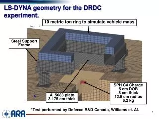
LS-DYNA geometry for the DRDC experiment. 10 metric ton ring to simulate vehicle mass. Steel Support Frame. SPH C4 Charge 5 cm DOB 8 cm thick 12.5 cm radius 6.2 kg. Al 5083 plate 3.175 cm thick. *Test performed by Defence R&D Canada, Williams et. Al. SPH simulation of DRDC experiment.

E N D
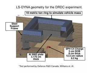
LS-DYNA geometry for the DRDC experiment. 10 metric ton ring to simulate vehicle mass Steel Support Frame SPH C4 Charge5 cm DOB8 cm thick12.5 cm radius6.2 kg Al 5083 plate3.175 cm thick *Test performed by Defence R&D Canada, Williams et. Al.
SPH simulation of DRDC experiment. Measured displacements: 30.0 cm center, -5.0 cm at edge.
ALE simulation of DRDC experiment. Soil Contours
DRDC plate deformation calculated from the LS-DYNA SPH simulation. Measured displacements: 30.0 cm center, -5.0 cm at edge.
DRDC plate deformation calculated from the LS-DYNA ALE simulation. ~25 ± 2cm, depending on soil compaction compared to 30 cm measured.
Model geometry for the dynamic shell buckling airblast analysis. Planar pressureload ALE air Steel plugs(constrained translation) Aluminum shell(tied to plugs)
Air Blast Analysis Results Test* Calculation • *Photo from Lindberg and Florence, “Dynamic Pulse Buckling,” 1987
Contours of pressure during blast-vehicle interaction. (a) t = 0.1 ms (b) t = 1.1 ms (c) t = 4.4 ms
Damage to vehicle at 13.0 ms. Vehicle Damage