Download
1 / 23
470 likes | 1.49k Views
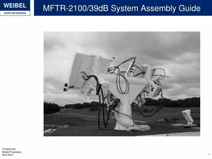
MFTR-2100/39dB System Assembly Guide. Pedestal, antenna & PSU. Power Supply. Camera and Mount (optional). OM-2100 Oscillator. MFDR-2100/40 Transmitting antenna. MFDR-2100/40 Receiving antenna. AP-2100/40. D-2100 Display. Pedestal Connections. Video Connection from antenna .

E N D
Pedestal, antenna & PSU Power Supply Camera and Mount (optional) OM-2100 Oscillator MFDR-2100/40 Transmitting antenna MFDR-2100/40 Receiving antenna AP-2100/40 D-2100 Display
Pedestal Connections Video Connection from antenna Warning Light Signal Connection from antenna AC Power from Pedestal to other external unit Signal Connection to RTP AC Power from Pedestal to Power Supply Control Connection to Antenna External Display Connection Warning Light Connection from Pedestal Trigger connection to External trigger Mains Power connection to Pedestal Ethernet Connection to RTP Camera Connections to Camera
Tx Antenna Connections Power Cable Connections to pedestal Oscillator Cable Connection Control Cable Connection Power Cable Connections to pedestal
Rx Antenna Connections Frequency 1 and 2 from Oscillator Control Cable to Oscillator Oscillator Cable Connection Control Cable Interconnection Signal Output to Pedestal Antenna Control Cable from pedestal
External devices connections AC Main power from Pedestal Power Supply Power Switch DC Power Connections to Antenna DC Power Connections to Antenna External Display Connection from Pedestal Camera Connections is dependent on Camera type The exact cable connections depend on exact model of antenna and pedestal. Other connection layouts may occur REMEMBER TO WRAP AND SECURE CABLE CAPS ON ALL CABLES Oscillator Control from Antenna Frequency 1 and 2 to Antenna Frequency 1 and 2 to Antenna
Outdoor items FOT-2 External Optical Trigger Device Trigger Cable connects directly to the Pedestal Trigger input
Protective Instructions In case the outdoor parts of the Tracking systems is left unattended (i.e. overnight) the following precautions should be taken • Secure the system safely in its position • Place the system in a secure Az & EL • Minimum stress and windload • Turn the power OFF • Detach data and signal cables connecting the pedestal to the RTP and other instrumentation. • In order to prevent damage from lightning etc. • Removing interconnections between antenna, pedestal and other items mounted onto the pedestal is not necessary. • Cover the pedestal and antenna with a waterproof tarp, to protect it. • In case high winds or severe weather is foreseen, special care should be taken to secure the system
AP-2100 Leveling • For system supplied on the MTB-2100 platform • Always ensure that the radar has freedom of movement as it will move to the extent of it capability in both azimuth directions • The Autolevel function can either run as a full auto-leveling or a simple re-leveling. • The fulllevelingextends the hydralic trailer legs fully and thenbeginitslevelingprocess • The re-leveling simple beginsitsleveling procedure from the current leg position
Aligning Radar to North B A C Insert the position of the Radar and Reference point into the position definition manager (in GPS or Cartesian, with 0 coordinate turn) Use beacon to true track to or alternatively point the system at the reference point using the scope (or camera) Use the ”Go to” function and enter the reference point (see A) Choose the sensor that is pointing to the reference point and push Adjust Azimuth Angle Offset (see B and C) System is now aligned to north
Aligning to Line of Fire B A C Use beacon to true track to or alternatively point the radar at the reference point using the scope (or camera) Insert the position of the Launcher into the position definition manager (in GPS or Cartesian) with a coordinate turn equal the line of fire according to north Update the Radar and local point with the same coordinate turn as the Launcher. Use the ”Go to” function and enter the reference point (see A) Choose the sensor that is pointing to the reference point and push Adjust Azimuth Angle Offset (see B and C) System is now aligned to line of fire
Trailer Connections Controller and Data Connection Display Cable Warning Lights Cable
Cables conneted to RTP-2100 Data - CAB314 Signal - CAB124
KVM Switch for RTDS-2100 & IC-2100 Operation • The IC-2100 & RTDS-2100 may be operated from a single workstation (Monitor/Keyboard/Mouse) • Once running the RTDS-2100 are controlled and monitored from the WinTrack software running on the IC-2100 Mouse Monitor To IC-2100 & RTDS-2100 Keyboard To toggle PC Press Scroll Lock “twice” (“SCroll Lock” - “Scroll Lock”) (iOGear KVM Switch)
The System Block and their function OUTDOOR COMPONENTS • MFDR-2100/xx: Multi Frequency Doppler Radar • OM-21xx: oscillator Module • AP-2100: antenna Pedestal • PS-xxxx: System Power supply • Tripod: For pedestal & Antenna • FOT-2: Muzzle Flash detector • Interconnection cables • System cables on drums (Data & control) INDOOR COMPONENTS • RTP-2100: Real Time Processor • IC-2100: Instrumentation Controller (WinTrack Computer) • RTDS-2100: Real Time Data Storage Computer
MFDR-2100/xx: Multi Frequency Doppler Radar Dependent on model • 39, 40,42 or 43 dB Antenna gain • 320 or 640 Watt transmit power • Multi Frequency (MF) Direct ranging • Frequency Modulated (FM) • The antenna is mounted on and powered from the AP-2100 Pedestal • Aligned to the line of fire or other reference coordinate system Output: • 8 (I/Q) Doppler analogue signals
OM-21xx: X-band Oscilaltor Module • Integrated with the MFDR-xxx Antenna Receiver • This High Quality solid state oscillator generates the X-band frequency utilized in the antenna • Controlled from the RTP through the AP Versions • S : Single frequency • D : Multi Frequency for MF-CW and FM-CW (option)
AP-2100: Antenna Pedestal • Provides: • Support for the MFDR-2100/xx Antenna • Bi directional pointing (Azimuth & Elevation) • System levelling sensor • System interfaces • Operation: local from keyboard (for alignment and levelling) • Provides: • Multi Frequency (MF) Direct ranging (option) • Frequency Modulated (FM) CW (option) • The antenna is mounted on and powered from the AP-2100 Pedestal • Aligned to the line of fire or other reference coordinate system Input: • 8 (I/Q) Doppler analogue signals • Analogue trigger form Flash detector Output: • 8 (I/Q) Doppler analogue signals • System Trigger
Fot-2 Optical Trigger • IR trigger detects the muzzle flash and provides accurate system trigger • Connected to and powered from the AP-2100 • Output: 1 channel diffeerential -7 V to + 7 V • Typical trigger level: 0.5 Volt
RTP-2100 Real Time Processor • The RTP-2100 is at the center of the tracking system • Located in the operation shelter with the IC-2100 & RTDS-2100 computers • The RTP-2100 performs all real time data processing tasks including: • Digitization of the analogue Doppler signals from the antenna • Streaming of the digitized Doppler data to the RTDS-2100 • Real Time FFT analysis and target tracking (Single or Multiple objects) • Real time control (direction) of the AP-2100 pedestal • System interface to the WinTrack operator console • INPUT • 8 Analogue Doppler signals (16 with MF option) • IRIG time code (optional) • Cuing data from designation tracking station • OUTPUT • Digitized Doppler to RTDS computer (Fiber link) • Real Time tracking info to WinTrack operator console • Cuing data to other tracking stations • Real Time DTI information to RTD computer (optional) • Interface to VT-2100 Video Tracker (optional) • Etc.
IC-2100 Instrumentation Controller • The IC-2100 or WinTrack computer provides the main operator console for the system • Interfaces to all system components • Perform post processing analysis on recorded data
RTDS-2100 Real time Data Storage • The RTDS-2100 application runs on a dedicated storage computer • Digitized real time Doppler data are streamed directly to the hard drive of the RTDS-2100 computer for later analysis • The RTDS-2100 application is controlled and monitored from the WinTrack operator computer (IC-2100)


![LAB [ 2 ]](https://cdn1.slideserve.com/2335586/lab-2-dt.jpg)