Download
1 / 26
320 likes | 580 Views
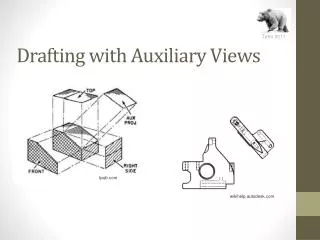
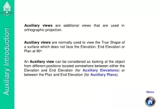
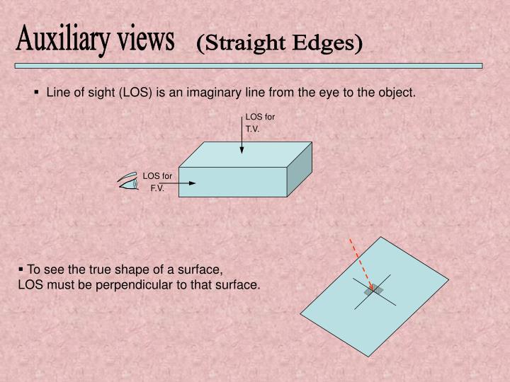
LOS for T.V. LOS for F.V. Auxiliary views. (Straight Edges). Line of sight (LOS) is an imaginary line from the eye to the object. To see the true shape of a surface, LOS must be perpendicular to that surface. LOS (T.V.). 1. 2. A. 4. 8. 3. 5. 7. 6. Take an object as follows :.

E N D
LOS for T.V. LOS for F.V. Auxiliary views (Straight Edges) • Line of sight (LOS) is an imaginary line from the eye to the object. • To see the true shape of a surface, LOS must be perpendicular to that surface.
LOS (T.V.) 1 2 A 4 8 3 5 7 6 • Take an object as follows : LOS (L.S.V.) LOS (F.V.)
2,7 1,8 A 3,6 4,5 T.V. 2,1 1 2 A A 4,3 3 4 7,8 5,8 6,7 6,5 F.V. L.S.V. • The Front, Top and Side Views are called the Principal Views. (Orthographic Projection) • Auxiliary View (or Extra View) is any view which is not one of the principal views. • Auxiliary view can be drawn from other views. • If you want to draw the true shape of surface A ( an auxiliary view of surface A) . need to choose LOS that is perpendicular to surface A. LOS for Aux. V. of surface A
1 2 2,1 1 2 A A A 4,3 3 4 4 7,8 8 5,8 6,7 6,5 F.V. L.S.V. (View 2) (View 1) 3 5 7 6 • Procedure to draw auxiliary view from 2 given views: 1- Label all corners for the two given views. 2- Draw projection lines between the two given views. 3- Choose LOS for the Auxiliary view (from view 1)
1 LOS for Aux. V. of surface A LOS 2 A 4 8 3 5 7 6
LOS for Aux. V. of surface A 1 LOS 2 x A 4 8 3 5 7 x 6
RL1 2,1 1 2 LOS A 43 3 4 7,8 5,8 6,7 6,5 F.V. L.S.V. RL2 (View 2) (View 1) 4 - Draw a reference line RL1 perpendicular to LOS (OFFSET and Extend)) 5 - Draw a second reference line RL2 perpendicular to the projection lines between the two views (choose it close to view) (OFFSET and Extend)
2,1 1 2 LOS A 43 3 4 7,8 5,8 6,7 6,5 F.V. L.S.V. (View 2) (View 1) RL1 RL2 6 - Draw projection lines // LOS from Each Corner to the reference line RL1 using SNAP TO perpendicular
d1 d2 1 2 A 3 4 1 d1 d2 8 2 4 RL1 5 7 3 2,1 LOS 6 4,3 7,8 5,8 6,7 6,5 F.V. L.S.V. RL2 (View 2) (View 1) 7 - From Toolbars add Inquiry then use DISTANCE to measure from view 2 (example d1, d2 ) 8 - Transfer these distance using OFFSET // RL1 for each corner 9- Extend the projection lines to the offset lines
1 d1 d2 8 2 4 RL1 d1 5 d2 7 3 2,1 1 2 LOS 6 A 4,3 3 4 7,8 5,8 6,7 6,5 F.V. L.S.V. RL2 (View 2) (View 1) 9 - Label corners on transfer points.
LOS for Aux. V. of surface A 1 LOS 2 x A 4 8 3 5 7 x 6
1 2 d1 d2 1 A 2 4 A 8 3 4 3 5 7 6 1 d1 d2 8 2 4 RL1 5 7 3 2,1 LOS 6 4,3 7,8 5,8 6,7 6,5 F.V. L.S.V. RL2 (View 2) (View 1) 10- Join all points to auxiliary view. To ensure that no edges have been missed, count the number of surfaces; loop each surface in turn, checking that all points are connected. Use solid lines to showing lines and dashed lines for hidden lines.
1 2 A 4 8 3 5 7 6 1 8 2 4 RL1 5 7 Complete Auxiliary View showing the true shape of Surface A 3 2,1 1 LOS to A 2 6 A A 4,3 3 4 7,8 5,8 6,7 6,5 F.V. L.S.V. RL2 (View 2) (View 1) • To draw the True shape of surface A, choose LOS which is perpendicular A. and repeat steps 1-10. (you will get an auxiliary view of the true shape of surface A).
Partial Auxiliary Views In the previous examples, we have drawn complete auxiliary views of the object. • Some times it is not necessary to draw complete auxiliary view, but only • an auxiliary view of only one surface in order to find its true shape. • This auxiliary view which shows only part of the object and not • the whole object is called “Partial Auxiliary View”.
1 2 3 RL1 Partial Auxiliary View showing the true shape of Surface A 4 2,1 1 LOS to Surface A 2 A A 4,3 4 3 7,8 5,8 6,7 6,5 F.V. L.S.V. RL2 (View 2) (View 1) • Example : draw the true shape of surface A as partial auxiliary view: repeat steps 1-10 but only for the corners of surface A (corners 1,2,3 and 4).
Surface A LOS E Auxiliary Views (Curved Edges) The same procedure (steps1-10) discussed before applies for curved edges. However, curved edges have no corners, so we take points on the curved edges and treat them like corners. The more points we take, the better the drawing of the Curved edges. Take the following examples. Surface A Draw a true shape of surface A ( i .e we need an auxiliary view where LOS is Perpendicular to surface A.
6' 5' 7' 8' 4' 9' 3' 10' 2' 11 + 1 2 10 3 9 4 8 5 7 6 1 2 3 4 5 6 7 8 9 10 11 1 - choose points on curved edges • connect projection lines between views • -Choose LOS ( in this case LOS is perpendicular to surface A to get true shape)
7' 6' 5' 8' 4' 3 9' 3' 10' 2' - Draw RL1 perpendicular to projection lines // LOS 11 + 1 • Draw RL2 perpendicular to projection lines • between the two views. 2 10 3 9 4 8 5 7 6 RL2 1 2 3 4 5 6 7 8 RL1 9 10 11
7' 6' 8' 5' 4' 9' 3' 10' 2' 11 + 1 2 10 3 9 4 8 5 7 6 1 2 3 4 5 6 7 8 9 10 11 2 • Draw projection lines from chosen points • on curved edges parallel to LOS.
7' 6' 5' 8' 4' 9' 3' 10' 2' 11 + 1 2’ 1 3’ 4’ 5’ 2 10 6’ 3 9 4 2 8 7’ 5 7 6 RL2 8’ 3 9’ 4 5 10’ 6 7 8 11 1 9 2 10 3 4 5 6 7 8 RL1 9 10 11 4 - Measure distance from RL2 - Transfer distance to RL1
7' 6' 5' 8' 4' 9' 3' 10' 2' 11 + 1 2’ 1 3’ 4’ 5’ 2 6’ 10 3 9 4 7’ 8 5 2 7 6 RL2 8’ 3 9’ 4 10’ 5 6 7 8 11 1 9 10 2 3 4 5 6 7 8 RL1 9 10 11 5 - Connect points
6' 7' 8' 5' 4' 9' 3' 10' 2' 1 + 11 RL2 2 10 3 9 4 8 5 7 6 1 2 3 RL1 4 5 6 7 8 9 10 11 OR 3' - Draw RL1 • Draw RL1
6' 7' 5' 8' 4' 9' 3' 10' 2' 1 + 11 RL2 2’ 3’ 1 4’ 2 10 5’ 3 9 4 6’ 8 5 7 6 2 7’ 8’ 3 9’ 4 5 10’ 6 7 1 2 11 8 9 3 RL1 10 4 5 6 7 8 9 10 11 OR 4' - Measure distance from RL2 • Transfer distance to RL1
6' 7' 5' 8' 4' 9' 3' 10' 2' + 1 11 RL2 2’ 3’ 1 4’ 2 10 5’ 3 9 4 6’ 8 5 7 6 7’ 2 8’ 3 9’ 4 10’ 5 6 7 1 2 11 8 9 3 RL1 10 4 5 6 7 8 9 10 11 OR 5' • Connect Point
6' 7' 5' 8' 4' 9' 3' 10' 2' + 1 11 RL2 2’ 3’ 1 4’ 2 10 5’ 3 9 4 6’ 8 5 7 6 7’ 2 8’ 3 9’ 4 10’ 5 6 7 1 2 11 8 9 3 RL1 10 4 5 6 7 8 9 10 11 OR 5' • Connect Point