Download
1 / 29
290 likes | 408 Views
An Attempt to Evaluate Satellite LST Using SURFRAD Data. Yunyue Yu a , Jeffrey L. Privette b , Mitch Goldberg a a NOAA/NESDIS/StAR b NOAA/NESDIS/NCDC. Outlines. Motivation Data Sources Method Results Summary. Motivation. Satellite LST Validation Needs Needs

E N D
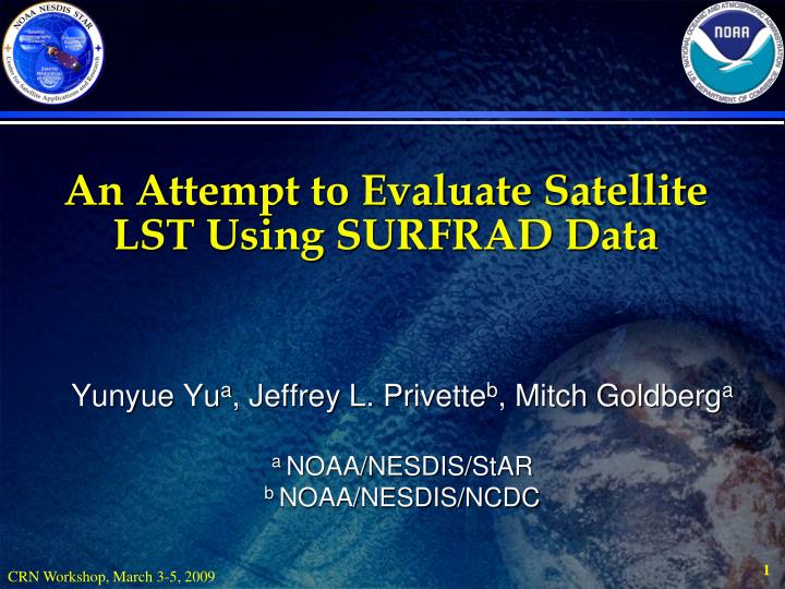
An Attempt to Evaluate Satellite LST Using SURFRAD Data Yunyue Yua, Jeffrey L. Privetteb, Mitch Goldberga a NOAA/NESDIS/StAR b NOAA/NESDIS/NCDC
Outlines • Motivation • Data Sources • Method • Results • Summary
Motivation • Satellite LST Validation Needs Needs • Over 30 years LST development at NOAA – Climate Data Record • Validation Needs for NPOESS/VIIRS LST Product • Five years Cal/Val plan: 2009 – 2013 • Core ground data source : 20 SURFRAD/CRN sites • Validation Needs for GOES-R/ABI LST Product • Pre-launch validation plan: 2009 – 2013 • Core ground data source : 10-15 SURFRAD/CRN sites • Validation Needs for GIMPAP LST product SURFRAD/CRN data plays critical role in NPOESS and GOES-R Programs !!
Motivation (2) • LST Validation Difficulties • In Situ data limitation • measurement difficulty: emissivity • Effect of cloud contamination • Partial or thin cloudy pixels • Spatial and temporal variations • Angle effect • New Method Exploration
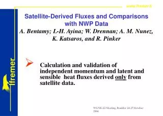
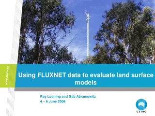
Data Sources Satellite and Ground Datasets GOES-8 and GOES-10 Imager data were applied in validating the LST algorithm using ground data from SURFace RADiation (SURFRAD) budget network stations Duration of Data: Jan 1 – Dec 31, 2001
Satellite Data Time Match-up (<15 mins) Geolocation Match-up Spatial Difference Test: T4 -- 3X3 pix STD, Visual -- 0.5 deg SURFRAD Data Manual Tuning Channel BT Difference Test: (Ts, T4), (T4, T2) (T4, T5) Matched Dataset Time Series Smoothness Check: Upwelling, Downwelling Irradiances Data Source (2) Match-up Flow Chart
Data Sources (3) Match-up Data Processing • The difference between the top of the atmosphere channel 4 brightness temperature from GOES satellite for the spatially closest pixel and the land surface temperature derived from SURFRAD measurements should be generally 5 K or less for clear sky conditions. • The standard deviation of the 3 by 3 pixel array GOES channel 4 brightness temperature should no exceed 1.5 K. • The absolute difference between GOES channel 4 and channel 2 brightness temperatures should not exceed 5 K. • The absolute difference between GOES channel 4 and channel 5 brightness temperatures should not exceed 1 K. • The time series curves of solar irradiance should be smoothly varying without distortions. • The time series curves of down-welling infrared irradiance also should be smoothly varying in time without any significant enhancement. • The average reflectance for the spatially closest GOES-pixel should be generally less than 40% except for snow conditions which can be mostly identified from sequence of hourly GOES images. Snow is more static than clouds. • Finally the 0.5 degree by 0.5 degree around the SURFRAD site must be visually clear of clouds to form coincident pairs of cloud-free SURFRAD and GOES data.
Surface Type Configuration Atmospheric profiles Input (looping) parameters MODTRAN Algorithm Coeffs. Regression of LST Algorithms Input parameters Start STD Error Of Algorithms Sensor Spectral Response Funs TOA radiances Filter of Data Distribution Accuracy Analysis Sensor Brightness Temperatures Sensor BrightnessTemperature Calculation plots Sensitivities Analysis tables Data Sources (4) Developing for Satellite LST Algorithm Simulation Process Regression Process Algorithm Selected Analyzing Process
Data Sources (5) Number of Match-up Dataset: GOES-8 and SURFRAD Overall: Large number for statistical significance.
Data Source (6) LST estimation from SURFRAD measurement
Method • Direct Comparison • Scatter Plots • Table of Statistics • Correlation Analyses • Two-measurement Comparisons
Method (2) Procedure of Direct Comparison GOES 8/10 data Satellite LST: Algorithms applied to GOES-8/10 data Ground LST: Derived from SURFRAD site measurements Duration: Jan 1 – Dec 31, 2001 Cloud filter Plots & Tables Algorithm: LST Calculation Match-up and Comparison Statistics Temperature : Femit=Fup-(1-e)Fdown Femit=esT4 Spectral Correction: T=T+dTpir - dTe dTpir=(dFepir/ Fe)(T/4) dTe=(T/4)(de/e) SURFRAD radiance
Results ---- Direct Comparison Validation Results:FORT PECK, 2001 Results for GOES-8 Results for GOES-10 Comparison of SURFRAD Estimated LSTs and GOES Retrieved LSTs
Results ---- Direct Comparison (2) Validation Results:Boulder, 2001 Results for GOES-8 Results for GOES-10 Comparison of SURFRAD Estimated LSTs and GOES Retrieved LSTs
Results---- Direct Comparison (3) Validation Results: direct comparison summary *weighted through each site Good: • Statistical significance • Two satellite validations • Accuracy satisfaction (average RMS=2.1 K) Issues: • Point-pixel difference • Emissivity inaccuracy • Cloud screen effectiveness
Method (3) Two-Measurement Method
Method (3) Two-Measurement Method
Results ---- Correlation Analyses Samples for GOES-8 LST vs SURFRAD: Bondeville Site Case Study
Summary • SURFRAD ground station data were used for GOES-R LST algorithm evaluation. • GOES-8, -10 Imager data were used as proxies of GOES-R ABI. • LST algorithm coefficients were derived from a radiative transfer simulation model (MODTRAN). • Match-up dataset of satellite and ground data were created carefully. • Direct comparisons indicate a promising algorithm accuracy. • Correlation analyses showed good algorithm precision • Further works will be performed using three-measurement comparison
Two-directions from GOES Satellites 135° W 75°W
LST Directional Effect in GOES-8 and -10 Imager Difference of LSTs observed by GOES-10 and GOES-8 imager at the same location of SURFRAD station Desert Rock, NV, 36.63ºN, 116.02ºW. The simultaneous observation pairs are about 2096. View zenith of GOES-8: 60.140 View zenith of GOES-10: 46.810
LST Directional Effect in GOES-8 and -10 Imager (2) Goodwin Creek, MS, observation pairs are about 510. View Zenith of GOES-8/-10: 42.680/61.890
LST Directional Effect in GOES-8 and -10 Imager (3) Boulder, CO, observation pairs are about 510. View Zenith of GOES-8/-10: 42.680/61.890
Fort Peck, MT. Data pairs: 912 Bondville, IL. Data pairs: 710 View Zenith of GOES-8: 62.420 View Zenith of GOES-10: 62.360 View Zenith of GOES-8: 48.120 View Zenith of GOES-10: 66.140 LST Directional Effect in GOES-8 and -10 Imager (4) Note the difference of the two sites
Daytime Scatter plot comparison of the GOES LST and the SURFRAD LST for all the match-up data in 2001, within 6 SURFRAD sites.
Nighttime scatter plot comparison of the GOES LST and the SURFRAD LST for all the match-up data in 2001, within 6 SURFRAD sites.
Dry atmos condition scatter plot comparison of the GOES LST and the SURFRAD LST for all the match-up data in 2001, within 6 SURFRAD sites.
Moist atmos condition scatter plot comparison of the GOES LST and the SURFRAD LST for all the match-up data in 2001, within 6 SURFRAD sites.