Download
1 / 24
240 likes | 247 Views
LTU & Undulator Commissioning Plans Heinz-Dieter Nuhn, SLAC / LCLS May 14, 2008. Overview Pre-Beam Checkouts LTU to Dump Commissioning (No Undulator Segments) Undulator Segments Commissioning Characterization of Spontaneous Synchrotron Radiation Characterization of SASE. J. F. M. A. M.

E N D
LTU & Undulator Commissioning PlansHeinz-Dieter Nuhn, SLAC / LCLSMay 14, 2008 • Overview • Pre-Beam Checkouts • LTU to Dump Commissioning (No Undulator Segments) • Undulator Segments Commissioning • Characterization of Spontaneous Synchrotron Radiation • Characterization of SASE 1
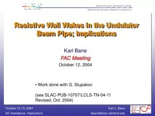
J F M A M J J A S O N D J F M A M J J A S O N D J F M A M J J A A M 2008 2009 2010 Down PPS LCLS Installation and Commissioning Time-Line First Light in FEE First Light in FEH PPS Cert. LTU/Dump LTU/Und/Dump Install Undulator Seg. Install X-Rays in NEH CD-4 (7/31/2010) FEE/NEH Install FEH Hutch BO FEH Install PEP-II run ends now LTU/Und Comm. Linac/BC2 Commissioning Re-commission Inj/BC2 to SL2 NEH Operations/ Commissioning FEE Comm. April 18, 2008 2
2008 2009 Beam-Based Commissioning A B C A: LTU – Dump B: Undulator Segments C: Spontaneous X-Rays D: SASE e--Beam D X-Ray 3
LTU/Undulator e--Beam Commissioning Blocks • Installation and Conventional Alignment (=>Nov 08) • All beamline components except Undulator Segments • Pre-Beam Checkouts (Checklists will be prepared) (Nov-Dec 08) • LTU Section • Magnet Polarities / Motion (OTR, Collimators, Wire-scanners) / etc. • Undulator Section • Magnet Polarities / Motion (Girder, BFW, Slide) / ADS Calibration / etc. • Pre-Undulator Commissioning with Beam (Jan 09 – Mar 09) • LTU Section • Undulator Section • Beam-Based Alignment / Motion Control / Beam Containment / etc. • Beam Dump Section • Installation of Undulator Segments (Mar 09) • Undulator Commissioning with Beam (Mar 09 – Apr 09) • Beam Based Alignment / Undulator Slide Functions / Beam Stability A B 4
LTU-to-Dump Pre-Beam Checkouts (Nov-Dec 08) • Undulator Hall HVAC System checkout (before Girder installation) • ADS (WPM & HLS) commissioning • ADS Control System checkout • EPICS Control System Checkout • Network Configuration of IOC's • Timing System • Communication with ADS Checkout • Verification of individual Device Operation • Magnet Power Supplies and Interlocks • Magnet Polarity Checkout • Dipoles • Quadrupoles • Correctors (where power supplies available) • BPM Cable Checkout • Motion Checkouts • Movable Collimator motion • Wire Scanner motion & calibration • Beam Finder Wire In/Out motion (BFW01 – BFW33) • Girder Motion Control checkout (33 Girders using external pos. sensors) • CAM Mover motion checkout • Transverse slide motion checkout • Compound motion checkout (Smooth beamline motion, System re-pointing) 5
LTU Commissioning with Beam (Jan-Mar 09) A • Perform radiation surveys in FEE, etc with beam in the dump (Stan Mao, et al.) • Checkout BPMs (timing, scale, sign errors, etc.) • Test MPS (toroid collimators, BPMs, loss monitors, magnets, trip the beam, etc?) • Checkout optics using beam oscillation data (does a betatron oscillation fit the model well everywhere? – backwards quads?) • Test/checkout BYKIK and its abort dump and logic (MPS). • Test/checkout new OTR screens/cameras (OTR30, OTR33, and OTRDMP). • Test/checkout new wire scanners (WS31, 32, 33, 34). • Test/checkout new adjustable collimators (CEDL1, CEDL3, CX31, CY32, CX35, CY36) • Commission new energy and launch feedback loops. • Characterize beam, etc. 6
Undulator Beamline Commissioning to Main Dump with Beam but without Undulator Segments (Jan-Mar 08) A • Commission Radiation Monitors • Get Beam through Undulator vacuum pipe with minimum losses. • Calibrate RF Cavity BPMs • Including sign determination. • Commission Girder Motion with Beam • Verify and calibrate steering effect of quadrupole motion • Calibrate motion parameters (gain, pivot points etc.) Check BPM offset tracking • Commission RF Cavity BPMs • Check charge dependent response over entire charge range • Use Girder Motion to calibrate position vs. readings • Check and correct optics matching over entire operational energy range • Commission Beam Based Alignment (BBA) • Develop saved configurations for three different energies. • Commission BBA GUIs and BBA procedure. • Commission Beam Finder Wires • Calibrate PMT signals. • Commission BFW GUIs (Alignment and scanning capabilities) • Commission ADS-based girder position stabilization feedback systems. • Commission Tune-Up Dump in preparation for commissioning with Undulator Segments 7
Install Undulator Segments (Mar 09) • Mount Undulator Segments onto girdersSegments will be stored in Undulator Hall before installation • System is designed to be Self-Aligning • Re-check girder motion control • Expect to install 3 Segments / day 8
First Beam Through Undulator Segments (Mar 09) B • Conditions for First Beam: • All Undulator Magnets Rolled-Out • Single Shot Operation (low charge) • Send single electron bunch through undulator • Read and evaluate as much diagnostics as possible along undulator(such as BPMs, beam loss monitors, toroids) • Identify and remove sources of beam loss – if any • Iterate • Goal: Get beam through vacuum chamber with minimum losses. • Reminder: Main Constraint is to Protect Undulator from Radiation Damage 9
First Undulator Segments Commissioning (Mar – Apr 09) • Undulator Segments still in Roll-Out position • Run BBA • Roll-In Individual Undulator Segments • Transport beam through individual Undulator SegmentsStart at slot #33 (last Undulator Segment) • Check and correct trajectory change. • Run BBA with Undulator Segments inserted. • Check Segment alignment with BFWs B 10
Commissioning of X-Ray Diagnostics (May – Jun 09) • Direct Imager • Slit • Solid Attenuator • Gas Attenuator • Gas Detector • Beam-Based K Measurement Components Minimum Requirement X-Ray Diagnostics is located after last Undulator Segment in Front-End Enclosure (FEE) See presentations by Tompkins and Bionta 11
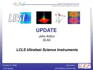
X Ray Diagnostics (FEE) 5 mm diameter collimators Soft X-Ray Offset mirror system Gas Detector Hard x-ray Monochromator (K Spectrometer) Direct Imager Solid Attenuator NFOV Slit Hard X-Ray Offset mirror system Total Energy Thermal Detector e- WFOV Gas Detector Start of Experimental Hutches Muon Shield Gas Attenuator See presentations by Tompkins and Bionta 12
Characterization of Spontaneous Radiation (May – Jun 09) • Initially at 1.5 Å to reduce damage issue • Start at low charge • Repetition rate of 10 Hz or lower will be sufficient • Start to characterize radiation at last undulator Measure: • total spontaneous energy / pulse • spontaneous beam direction • temporal variation in spontaneous beam parameters • spatial distribution around first spontaneous harmonic • spontaneous radiation spectrum • wavelength of first harmonic • first harmonic wavelength spread • Characterize radiation from each individual Undulator • Measure relative K of Undulator pair. C Limited capability using K Spectrometer 13
Measure synchrotron radiation spectrum produced by two undulator segments, and scan K of one segment K’s are matched when spectrum has the steepest slope on high energy side of 1st harmonic peak. Match segments pair-wise until all segments are measured. K Measurement: 2-Segment Scheme C undulator segments (33 total) segments under test 14
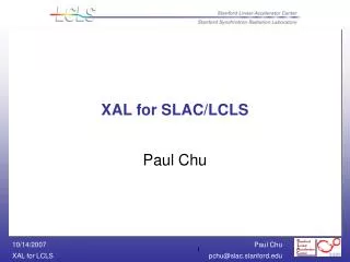
Angle-Integrated Spontaneous Spectrum for 2 Undulators with DK/K = -0.2 to +0.2% C Dj = 0 Simulations P. Emma Dx = 3 mm DK/K = +0.2% • 0.1% rms e- energy jitter • 0.003% rms e- energy meas. resolution • 2% rms charge jitter • 0.5% charge meas. res. • 0.5s rms angle jitter • 105 photons/pulse/0.01% • 100 photon noise • 100 beam pulses with natural energy jitter only DK/K = 0% ~106 photons/nC/0.01%BW DK/K = -0.2% 15
Characterization of SASE (Jul – Aug 09) D • Initially at 15 Å to maximize SASE gain • Start with reduced number of undulatorsRedo BBA after change of undulator configuration • Verify that electron beam meets requirements • Use Laser-Heater modulation to control gain(7 Hz Lock-In Detection) if necessary • Repetition rate of 30 Hz (to support Lock-In Detection) • Find SASE signal using Direct Imager • Optimize gain (through electron beam quality and BBA) • Measure gain length etc… 16
FEL Measurements D • Measurements along undulator • Intensity (LG, Saturation) • Measurements after undulator • Photon wavelength • Photon wavelength spread • Pulse intensity • Pulse duration • Pulse centroid and direction • Spatial distribution • Jitter Saturation Exponential Gain Regime Undulator Regime 1 % of X-Ray Pulse Electron BunchMicro-Bunching 17
SASE Characterization with FEE Diagnostics D • X-ray beam diagnostics located in FEE, down stream of last Undulator Segment • Obtain necessary z-dependent information through SASE gain shut-off at selectable points along undulator line by • Introduction of trajectory distortion or • Roll-out of individual undulator segments 18
Measurement of SASE Gain Length withTrajectory Distortion D GENESIS Simulations by Z. Huang Quadrupole Displacement at Selectable Point along Undulator 19
Measurement of SASE Gain Length Using Rollout D Undulator Segments can be rolled-out by remote control. Roll-out will start at the last Segment. Roll-out Segments will not effect radiation produced by earlier segments. 20
Summary • Plans for LTU/Undulator commissioning have been worked out and include • Detailed pre-beam checkout • LTU-Main Dump commissioning without Undulator Segments installed. • Installation of Undulator Segments. • Undulator Segment Commissioning • Characterization of Spontaneous Radiation will be combined with commissioning of X-Ray diagnostics suite in FEE • Beam based K-measurement method included. • Characterization of SASE will start at 15 Å • Gain length measurements will use FEE x-ray diagnostics combined with z-dependent SASE gain cut-off A B C D 21
Application Software Development • LTU Emittance Measurement (Loos – extension of existing GUI) • Undulator Steering and re-Pointing (Nuhn) • Beta-Matching into the Undulator – with variable mean beta (Limborg) • Beam-Based Alignment of the FEL Undulator (Loos) • Beam-Finder Wire Application – Centering & Emittance (Loos/Nuhn) • K-Measurement Application (Emma/Nuhn) • There will probably be more … 23
Undulator Segment and TLD Replacement Program 2009 2010 24