Download
1 / 12
120 likes | 128 Views
Learn about complex power and power factor correction in circuits, including the calculation of real and reactive components, the use of power triangles, and the conservation of power. Discover how power factor correction can improve efficiency and reduce losses. Explore the application of power meters and the cost implications of electricity consumption.

E N D
Complex Power, Power Conservation, Power Factor Correction, and Applications Circuits IIEE221Unit 11Instructor: Kevin D. Donohue
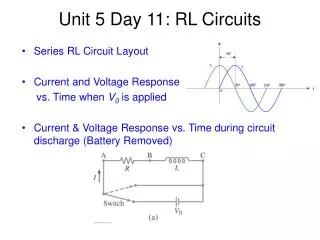
Complex Power • Complex power has real and reactive components. • Denote the sinusoidal voltage and current in a load by: • Then the complex power is expressed as:
Complex Power • The real and imaginary terms of complex power represent the real (P) and reactive (Q) components of the power: • Note that previously described power quantities can be obtained from complex power
Complex Power with Impedance • Load impedance can be expressed as: • The above relationship can be used to express power in terms of load impedance and either current or voltage magnitude.
Power Triangle • The real and reactive terms of a load (R, X) can be represented by a triangle modeling the vector addition. The legs of the triangle are the real (P) and reactive (Q) components and complex power: Phase of Impedance
Power Triangle • The power triangle provides a graphic representation of leading and lagging properties of the load:
Conservation of Power In a given circuit the complex power absorb (denoted by positive values) equals the complex power delivered (denoted by negative values). For a circuit with N elements the sum of all power is zero: Note that the above is only true for the real and reactive components. This is not true for apparent power.
Power Factor Correction • For a fixed generator voltage and load average power, the output current should be minimized to limit losses over the power line. This is done by adding reactive components to the power systems to bring the PF to 1 (or close to it).
Power Factor Correction • For an inductive load (PF lagging) a purely capacitive load can be added to the line to bring the power factor closer to 1. Show that for a load with PF = x1 lagging and apparent power S1 = IrmsVrms that a new power factor of PF = x2 is achieved by placing a capacitor in parallel with the load (shunt) such that:
Power Factor Correction • For a capacitive load (PF leading) a purely inductive load can be added to the line to bring the power factor closer to 1. Show that for a load with PF = x1 leading and apparent power S1 = IrmsVrms that a new power factor of PF = x2 is achieved by placing a shunt inductor across the load such that:
Power Meters Power meters must simultaneously measure the voltage (in parallel) and the current (in series) associated with load of interest. The meter deflection is proportional the average power.
Electricity Consumption Cost • The kilowatt-hours (kWh) to a customer is measured with a kWh meter corresponding to the average power consumed over a period of time. • (Energy Charge) The cost/rate of the kWh may vary depending on when the power is used (high vs. low demand), and how much total power has been consumed (cost may go down after so many kWh used). • (Demand Charge) A fixed overhead amount is charged simply to maintain the power delivery system, even if you use no power. • A penalty may also be imposed for having a pf below a set figure (i.e. 0.9) since it requires larger currents and the unmetered losses in the line to the customer.