Download
1 / 41
420 likes | 700 Views
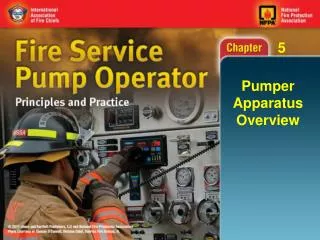
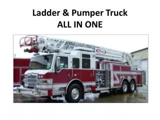
Pumper Operations. Why do we need to be concerned about being good pump operators? When we are good pump operators the personnel working the hand lines are getting the right pressures to fight the fire and protecting us for legal reason.

E N D
Pumper Operations • Why do we need to be concerned about being good pump operators? • When we are good pump operators the personnel working the hand lines are getting the right pressures to fight the fire and protecting us for legal reason. • The truck is being used to its proper flows and not exceeding the maximumrating on the ULC label 100%75%50%
Items we will be reviewing in this lesson • Types of gages found on a truck • Knowing on how to put the pump into operation • Different types of pumps • Different types of priming devices • What is the main purpose of a pumper • The immediate need for water • Influence on the positioning the pumper
Water supply sources • Types of hookups to supply a pumper • What is the Difference between pumping and relay pumping • Friction loss • Flows of Nozzles • Fire ground calculation for hydraulics • The use of relief valve and how it works • The differences between a relief valve and a governor
KNOWING HOW TO PUT THE PUMP INTO GEAR • Stop the truck in the place that you need, put in neutral, put the brakes on, take the transmission out of gear and place the pump in gear by way of a transfer valve, then put the transmission into gear - i.e. 5th/4th gear or drive depending on the unit and way it is manufactured
Types of Gages found • Oil pressure • Tach RPM - you should check it with the cab to see if they match or close • Engine coolant • Water tank level • Voltage
Compound and Pressure Gauges • Compound\Vacuum - this gage is found on the pump panel and reads on the intake side of the pump. This gage is capable of reading a negative & positive pressure vacuum
Gages continued • This gage when working shows you how much water pressure being pulled at a draft in negative pressure. Once you have a flow of water coming in it shows you a Residual pressure that is water for you to use. You do not want to go below 140kpa residual pressure as you may cause pump damage or cavitation of the pump
Pressure gage on the discharge side of the pump shows you the water pressure on the output side of the pump.
Different Types of Pumps • Centrifugal Pumps • Positive Displacement Pumps ie: Piston Pumps or Rotary Pumps • The pumps on this depart are Centrifugal • The Operation of a centrifugal is water enters the the eye or center of the pump and the impeller rotates with the vanes on the impeller and forces the water out the volute making pressure the faster it turns.
Pumps continued • The volute casing is shaped smaller on one side and then gets larger at the discharge side - this is how it makes it pressure. • Centrifugal Pumps can’t pump air so these types of pumps need a priming device. • We didn't talk about the other types of pumps hear because we don’t have any of them
Priming Devices • Successful drafting depends the ability to create a lower pressure within the pump. • This results in water being forced up the intake hose into the pump by atmospheric pressure. As stated earlier centrifugal can’t pump air this is why we need primers. • When pulling a prime pull it for maximum 30sec a good prime is 10-15 sec • With a RPM of 900-1200 • Draft sites options 3,meters of lift vs. 6, meters of lift for best water delivery to pump is 3,meters
Different types • Positive displacement, exhaust, vacuum • Positive Displacement primers are rotary gear or vane pumps driven by small electric motor or other mechanical means from the pump transfer gear case. • Possible now are Air primers low maintenance
Exhaust Primers • Exhaust primers are found on portable pumps - they work by diverting the exhaust gases to a chamber where the velocity of the gases pass through a venturi creating a vacuum and discharging it to the atmosphere. • Exhaust primers must be kept in good shape to work.
Vacuum Primers • Vacuum primers are the simplest type of primer it use - the vacuum already present in the intake of any gas powered motor. • These types of primers are not used as much anymore • Danger of this was pulling water back into the motor and killing the motor found on older trucks
Vacuum Primers Continued • Vacuum primers create 2 dangers, 1st the intake manifold contains explosive gases that could be drawn into the pump and cause damage. 2nd when prime has been made, water could be drawn through the pump into the intake manifold causing engine damage
What is the Main purpose of a Pumper • Provide water at adequate pressure for firefighting streams • What is the immediate need for water • Where are the water sources going to come from
Purpose of Pumper Continued • Knowing how much water you have on the truck and where to find other water sources that can be used. If you need a water supply from the other source lay the line to the side of the road or driveway to allow other units in.
Influence on positioning the Pumper • Should stop the unit short of the building on fire and find the best spot to place the truck. Such as keeping the truck upwind and away from a collapse zone of a building. • Exposures – watch for any to protect and being able to deploy lines to look after this. • This gives you ideas where you would place equipment.
Position Pumper Continued • Watch for the terrain you might have to work in - look for hard packed ground. If fighting any brush or grass fire, try to get into the burned area with the equipment as the fire will not burn back on you. Then work from inside to out to put this type of fire out. Watch the ground and remember what the weather has been before.
Water Sources • Water Supply Sources • Water Supply Tankers • Pressurized sources, hydrants, • Static sources, lakes, ponds,creeks,portable tanks,pools, • On the fire ground the pumper could be fed by the way of supply line running up the side of the laneway from water tankers road
Or another pumper could be placed at the water source and the water pushed up the supply lines to the pumper at the scene.
Types of hookups • Drafting with a suction hose from a static source • Hooking a 2-1\2 or 4 inch supply line to a pressured source i:e hydrant, • Or as mentioned just before - from water tankers hauling water to the fire by the way of lines or dumping into a portatank.
The difference between tandem and dual pumping is: • Dual pumping is when more than one truck can pump off the same hydrant because it is strong and high flow of water. The advantages - shorter hose lays - better use of the water available. Dual units are usually close together and intake to intake bring water into the first truck and then out to the 2 truck intake port.
Tandem Pumping • Relay pumping is when one truck is at the hydrant and feeds the other truck with the lines a distance away, so the way this works is the 1st truck takes the hydrant into its intake and pushes it through the pump and discharges through its discharge outlets to the 2nd truck or so on from there. If greater pressure is needed in a long lay you could have another truck involved.
Friction Loss: • All hose has friction loss and the numbers we will show you are easy for figuring out the friction loss in the line lays. We will show you the friction loss numbers for 1-1\2 - 38mm and 2-1\2 – 65mm inch hose on the next pages coming up. • All handline nozzles have a setting of 700kpa to be added to your friction loss
So a hose flowing 500-L\m ________30m \100ft_______________ • The friction loss is 270 per 1-1\2 hose per 30 m or 100ft • So for the right pump pressures on the panel should be with the nozzles that are flowing 700 n p. To figure this out for the flow above, would be 700 n p + 270 fl = 970 kpa.
The Guideline for 38mm\1-1\2 hose is 500L\M @270, 375L\M @170 • 250L\M@70, • 125L\M @20. • The guideline for 65mm\2-1\2 hose is • 950L\M @ 90, • 750L\M @ 60, • 550L\M @ 30 • 450L\M@ 20 • You will need to have to remember these for later we will help you with this
So a hose of 38mm flowing @ N.P of 700 flowing 500L\M and lay of 45m the pressure • needed on the P.P = 1105 • So a 65mm hose flowing @ N.P of 700 flowing 950L\M and lay of 60m the pressure needed on the P.P = 880 • We all will work through this on paper at the end of this learning part and you all will be given a card with the friction loss on it.
One thing to remember is that for every meter of height change we must + or -- 10kpa • Most of our nozzle that are on the trucks right now, flow 700Kpa. We do have some older steel nozzles found on units and that have select flows on them. • In the most part when you plan out your friction loss go with the higher flow.
Fire Ground Hydraulics Calculation • F.T 375L\M • 60m of 38mm 700 N.P • PP needed is 1040 • F.T 950L\M • 120m of 65mm 700 N.P • PP needed is 1060
F.T 250L\M • 90m of 38mm 700 N.P • PP needed is 910 • 75m of 65mm • 950l\m • 700n.p • with an elevation of 20meters • PP needed is 1125
90m of 65mm 30m of 38mm • on both 500L\M 700N.P • PP needed is 1240 • 75m of 38mm 500L\M • with a drop in elevation of 25 m 700N.P • PP needed is 1125
Relief Valve and what it does • The feature of a relief valve is it sensitivity to pressure change and its ability to relieve excessive pressure within the pump discharge. Protecting the firefighter hanging on the end of the hose lay if someone should shut down a line; the relief valve notices the change of pressure and opens.
The most common relief valve are spring controlled and set by a turn handle • You have to set valve to the Pump Pressure that is the highest you will be pumping at. • To set the relief valve turn the handle all the way to the left to the lowest setting and then turn it back right until the light goes out and then back a 1\4 turn - your truck is now protected
Relief valve continued • So a pump pressure of 1000 kpa - the relief valve is set to this - if you add another line and the pressure is going to be greater than 1000 kpa. • You will have to reset the relief valve to operate at the higher pressure or you will not be able to get it on the panel as the valve will operate at the set pressure from before
Relief Valve continued • It would be a good idea to leave the relief valve preset around 13 turns as the truck will be protected in around 1000-1300kpa of the unit. • As the Pump operator has lots to think about in the first few minutes of pulling on a scene • This shall be set as soon as the 1st line is flowing
The difference between a Relief Valve and a Pressure Governor are • The pressure governor is regulated by the engine throttle; it has a brain that notices the flow and the engine speed and controls the operation • As with the relief valve the operator has to set it and listen for any changes and reset if any lines are added or taken away.
Relief and Pressure Continued • And the governor looks after this for the operator once it has all been preset by department or the factory. • Or the department has had preset values put in the pressure governor for there hose lays they most use at scenes
Pressure Governors • To use a PG • When in draft mode set it in RPM and get your draft as you need some engine RPM to get your prime • Once you have your water and flowing change the PG to the Press mode you will have protection for your lines
This has been just an outline in being a good pump operator. • We will also practice this out on the fire ground using the things learned in this lesson • Happy and Safe Pump Operation