Download
1 / 34
370 likes | 735 Views
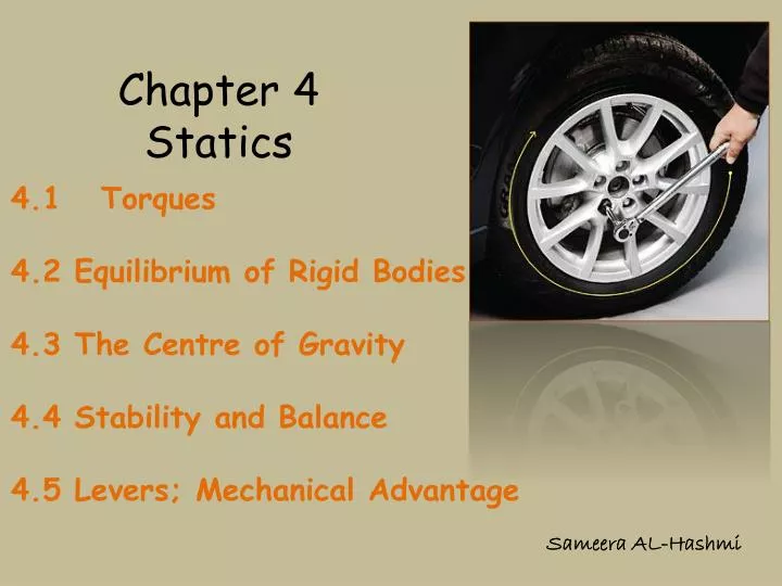
4.1 Torques 4.2 Equilibrium of Rigid Bodies 4.3 The Centre of Gravity 4.4 Stability and Balance 4.5 Levers; Mechanical Advantage . Chapter 4 Statics. Sameera AL-Hashmi. What Is Statics ? It is the study of the forces acting on an object that is in equilibrium and at rest.

E N D
4.1 Torques 4.2 Equilibrium of Rigid Bodies 4.3 The Centre of Gravity 4.4 Stability and Balance 4.5 Levers; Mechanical Advantage Chapter 4Statics Sameera AL-Hashmi
What Is Statics ? It is the study of the forces acting on an object that is in equilibrium and at rest. Importance of Statics To find the forces acting on various parts of engineering structures, such as bridges or buildings, or of biological structures, such as jaws, limbs, or backbones. To understand the force multiplication or mechanical advantage obtained with simple machines, such as the many levers found in the human body. Statics is based on the rigid body: an object that does not change its size or shape when subjected to a force.
4.1 Torques If a child applies equal but opposite forces F1 and F2 = ‐F1to opposite sides of a freely rotating seat, it will begin to rotate. Hence, it is not in equilibrium, even though the net force is zero, F = F1 + F2 = 0 The magnitude of the torque about point P is τ= r F sinθ r is the distance from a point on the axis of rotation to the point where the force acts on the object. q is the angle between r and F. SI unit: (N m) Torqueis the ability of a force to cause rotation.
Suppose we need to unscrew a large nut that rusted into place. To maximize the torque, we use the longest wrench available and exert as large a force as possible and pull at right angle. Example 4.1A mechanic holds a wrench 0.3 m from the center of a nut. How large is the torque applied to the nut if he pulls at right angles to the wrench with a force of 200 N? Solution: Since he exerts the force at right angles to the wrench, the angle θ is 90°, and sin θ =1 Thus the torque is τ= r F sinθ= (0.3 m)(200 N)(1) = 60 N m
Finding the magnitude of a torque using the lever arm: 1. Draw a line parallel to the force through the force’s point of application; this line (dashed in the figure) is called the force’s line of action. 2. Draw a line from the rotation axis to the line of action. This line must be perpendicular to both the axis and the line of action. The distance from the axis to the line of action along this perpendicular line is the lever arm (r⊥). 3. The magnitude of the torque is the magnitude of the force times the lever arm: τ= r⊥For τ= rF ⊥ where r⊥= r sinθand F ⊥ = F sinθ(the perpendicular component of the force).
Cross Product Definition The vector product or cross product of vectors A and B is a vector C which is written C = A × B MagnitudeC = AB sin Direction Vector C has a direction that is perpendicular to the plane containing A and B such that Cis specified by the right-hand rule; curling the fingers of the right hand from vector A to vector B, the thumb points in the direction of C.
Cross Product * Vector (cross) product is notcommutative A × B = - B × A Thus the order of the factors in a cross product is significant. This contrasts with ordinary algebra, where x . y = y . x holds and with vector addition, where A + B = B + A. These operations are commutative.
Cross Product Example 4.2The vectors in the figure are all in the plane of the page. Find the magnitude and direction of (a) A x A; (b) A x B; (c) A x C. Solution: a) IA x AI = A . A sin 0 = 0 The cross product of any vector and a parallel vector is zero. (b) The magnitude of A x B is IA x BI = A . B sin θ = (5)(4) sin 90° = (20)(1) = 20 We rotate our right palm from A toward B. Our right thumb then points out of the page. (c) The magnitude is IA x CI= A . C sin θ = (5)(4) sin 30° = (20)(0.5) = 10 Now when we rotate our right palm through 30° from A toward C, our thumb points into the page.
Using the right hand rule, we can find the direction of the torque vector. If we put our fingers in the direction of r, and curl them to the direction of F, then the thumb points in the direction of the torque vector. Direction of the Torque Clockwise torques The torques causing clockwise rotations are directed along the axis into the page ( negative vectors ) Counterclockwise torques The torques causing counter- clockwise rotations are directed along the axis out of the page (positive vectors )
Couples A Coupleis a pair of forces with equal magnitudes but opposite directions acting along different lines of action. ImportantPoints Couples do not exert a net force on an object even though they do exert a net torque. The net torque is independent of the choice of the point P from which distances are measured. The pair of forces applied tothe wheel is an example a couple.
Example 4.3 Two forces with equal magnitudes but opposite directions act on an object with different lines of action. Find the net torque on the object resulting from these forces. Solution: If we compute the torque about the point P in the figure, the torque resulting from the force at x2is τ2 = ‐x2F. (The minus sign indicates a clockwise torque.) The torque resulting from the force at x1is τ1 = x1F. The net torque is τ = τ1 + τ2 = x1F ‐ x2F = (x1 ‐ x2)F = ‐ lF The torque due to a couple is the same about every point.
4.2 Equilibrium of Rigid Bodies There are two conditions for the equilibrium of a rigid body: 1‐ The net force on the object must be zero, translational equilibrium 2‐ The net torque on the object computed about any convenient point must be zero. rotational equilibrium F = 0 • τ= 0 When two children balance on a seesaw, the heavier child must be closer to the pivot.
Example 4.4 Two children of weights w1 and w2 are balanced on a board pivoted about its center. (a)What is the ratio of their distances x2/x1 from the pivot? (b) If w1 = 200 N, w2 = 400 N, and x1 = 1 m, what is x2? (For simplicity, we assume the board to be weightless; this will not affect the result.) Solution: • a)The force N exerted by the support must balance their weights so that the net force is zero: • N‐w1‐w2 =0, N=w1+w2 • The torques resulting from the weights are τ1=x1 w1and τ2= -x2 w2 • τ =τ1+τ2= 0 • x1 w1‐x2 w2= 0 or x2/x1 = w1/ w2 • (b) If w1= 200 N, w2= 400 N, and x1= 1 m, then we must have • x2 =x1 (w1/ w2 ) = (1 m) (200 N/400 N) = 0.5 m
Applications to Muscles and Joints Generally a muscle is attached, via tendons, to two different bones . The points of attachment are called insertions. The two bones are flexibly connected at a joint, such as those at the elbow, knee and ankle. A muscle exerts a pull when its fiber contract under simulation by a nerve, but it cannot exert a push. The techniques for calculating forces and torques on bodies in equilibrium can be readily applied to the human body. This is of great use in studying the forces on muscles, bones and joints.
Example 4.6 A model for the forearm in the position shown in the figure is a pivoted bar supported by a cable. The weight w of the forearm is 12 N and can be treated as concentrated at the point shown. Find the tension T exerted by the biceps muscle and the force E exerted by the elbow joint. • Solution: • Applying the condition F = 0, • T‐ E – w = 0 • This contains both unknowns, T and E. Calculating torques about the pivot, E produces no torque, w produces a torque ‐(0.15 m) w, and T produces a torque • (0.05 m) T. Thus, τ = 0 becomes • ‐ 0.15w + 0.05T = 0 • The first equation then gives • E = T ‐ w = 36 N ‐ 12 N = 24 N • E is positive, so it is directed downward as initially assumed.
4.3 The Centre of Gravity • The centre of gravity of an object is the point at which the entire weight of the object is considered to act. • The torque produced by the weight of a rigid body is equal to that due to a concentrated object of the same weight placed at the centre of gravity . • .
Locating the Center of Gravity • One way to locate an object’s center of gravity is by means of suspension. An object always hangs so that its C. G. is directly below the point of suspension, since in this position the torque resulting from the weight about that point is zero. • The C. G. of a uniformly dense symmetric object is at its geometric center. • . The C. G. can be outside of an object, such as for a donut.
The C. G. lies on the vertical line through P1. • For less symmetric object, The C. G. also lies on the vertical line through P2. So it is located at the intersection of the two lines. The C. G. of the hammer is located inside the handle close to the hammer’s head.
The center of gravity of two point weights: X = (x1 w1+ x2 w2) / w wherew = w1+ w2 *Suppose that w1= w2 Then w =w1+ w2 = 2w1,and X = (x1 w1+ x2 w1) / 2 w1 = (x1 + x2) / 2 • Thus the C. G. X is the midway between the two weights (symmetric object) . If there are more than two weights, then the C. G. is X = (x1 w1+ x2 w2+ x3 w3 + . . .) / w wherew = w1+ w2+ w3 + . . . . • Mathematically :
Example 4.8 A weightless plank 4 m long has one concrete block at the left end, another at the center, and two blocks at the right end. Where is the center of gravity? Solution: The total weight is w = w1+ w2+ w3 = 4 w0 X = (x1 w1+ x2 w2+ x3 w3) / w = [0 + 2 w0 + (4)(2 w0)] /4 w0 = 2.5 m The center of gravity is between the center of the plank and the heavier end.
The Center of Mass The center of gravity, X = (x1 w1+ x2 w2+ x3 w3 + . . .) / w If w = mg then X involves masses instead of the weights, and it is called the center of mass ( C. M.). X = (x1 m1+ x2 m2+ x3 m3 + . . .) / m where m = m1+ m2+ m3 + . . . Note: the center of gravity is the same as the center of mass as long as g has the same direction and magnitude for each weight.
4.4 Stability and Balance Stability is a quality relating to the degree to which a body resists being upset or moved. Balance is a physical ability that may be improved through purposeful practice. Types of balance: • Static balance, when a person or an object remain over a relatively fixed base. • Dynamic balance, when a performer is in motion. Balance is not the same as symmetry and symmetry is not the same as balance.
Base of support: The supporting area beneath the object that includes the points of contact with the supporting surface and the area between them. Human Base of Support is the area under the feet (or shoes) including the area between the feet. This area is traced from toe to toe and from heel to heel.
The major factors that affect an object’s stability & balance: • The area of the base of support The larger the base of support, the more stable the object will be • The mass of the object The greater the mass, the greater the stability.
Position of the center of gravity: An object is in balance if its center of gravity is above its base of support. • The relation of the line of gravity to the edge of the base An object has balance depending on where the C. G. is in relation to the base of support (balance is less if the C.G. is near the edge of the Base of support).
The height of the center of gravity The higher the center of gravity, the more likely that an object will be out of balance.
4.5 Levers; Mechanical Advantage Simple machines, such as levers, pulleys, gears, and the wheel are designed to reduce the force needed to lift a heavy load. In each case there is an applied force Fa and a load force Fℓ is balanced. The mechanical advantage of a machine is the ratio of the magnitudes of the load force FL balanced by an applied force Fa. mechanical advantage = M.A. =FL/Fa A lever in its simplest form is a rigid bar used with a fulcrum. Fulcrum is the point or support on which a lever pivots.
Class I : The fulcrum lies between Faand FL. • Class II: The fulcrum is at one end, Faat the other end and FL lies between Faand the fulcrum. • Class III: The fulcrum is at one end, FL at the other end and Falies between FL and the fulcrum. Classification of Levers
Levers in the Human Body Muscles and bones act together to form levers. • Bones act as lever arms. • Joints act as pivots. • Muscles provide the applied forces to move loads. • Load forces are often the weights of the body parts that are moved or forces needed to lift, push or pull things outside our bodies.
Example 4.10 Suppose the load force FL on a class I lever has a magnitude of 2000N. A person exerts a force Fa= 500N to balance the load. (a) What is the ratio of the distances xaand xL? (b) what isthe mechanical advantage of this lever? Solution: (a) The torque due to Faisτa= - xaFaandthe torque due toFL isτL= xLFL.Forbalance,thesemustsumtozero,so xL FL - xaFa= 0 and xa/xL= FL / Fa= 2000/500 = 4 (b) The mechanical advantage of the lever M.A. =FL/Fa= 4
For all classes of levers the mechanical advantage can be expressed as a ratio of distances from the fulcrum, mechanical advantage = M.A. =xa/xL • If the forces are at right angle of the levers, in equilibrium the ratio of the magnitudes of the load force to the applied force is FL / Fa=xa/xL • With the forces at right angle to the lever the M.A. of class III levers is always less than 1 , and the M.A. of class II levers is always greater than 1.Class I levers can have an M.A. larger or smaller than 1.
The Human Spinal Column Spinal column is a third class lever with a very small mechanical advantage. Hence, bending over to pick up even a light object produces a very large force on the lumbrosacral disk, which separates the last vertebra from the sacrum ( the bone supporting the spine).
Since bending over without lifting a load puts a great stress on the spine, it should be avoided. If, instead, one flexes the knees but keeps the back vertical , then the centers of gravity of all the weights lie almost directly above the sacrum. Consequently their torques about the sacrum are small, and the muscles need not exert any appreciable force.
Homework Problems: 4.11, 4.18, 4.41, 4.45 and 4.55