Download
1 / 35
350 likes | 562 Views
TOPIC 4. Filters Design. 0 dB. Rp dB. -3 dB. - Ax dB. fc. fx. Rp dB. 0 dB. -3 dB. - Ax dB. fx. fc. Basic Filters 1. Lowpass. P assband: 0 — fc (Hz) Stopband: fx — ∞ (Hz). 3 dB (Cutoff ) Frequency : fc (Hz) Maximum Passband Attenuation : 3dB Passband Ripple : Rp (dB)

E N D
TOPIC 4 Filters Design
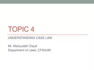
0dB Rp dB -3dB -Ax dB fc fx Rp dB 0dB -3dB -Ax dB fx fc BasicFilters1 Lowpass Passband: 0 — fc (Hz) Stopband: fx—∞ (Hz) 3dB (Cutoff ) Frequency : fc (Hz) Maximum Passband Attenuation : 3dB Passband Ripple : Rp (dB) Stopband Frequency : fx (Hz) Minimum Stopband Attenuation : Ax Highpass Passband: fc—∞ (Hz) Stopband: 0 — fx (Hz)
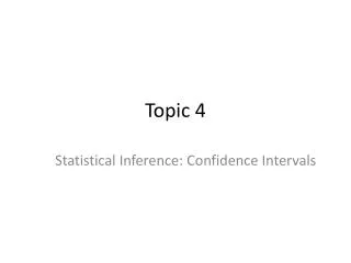
Rp dB Lower passband edge = fLp Upper passband edge = fHp Lower stopband edge = fLx Upper stopband edge = fUx Passband Bandwidth = fHp - fLp Passband Ripple = Rp dB Maximun Passband Attenuation = 3dB Minimum Stopband Attenuation = Ax Center Frequency = fo = fHp fLp 0dB -3dB -Ax dB fUx fLx fLp fo fHp fLp fLx fUx fHp fo Lower passband edge = fLp Upper passband edge = fHp Lower stopband edge = fLx Upper stopband edge = fUx Stopband Bandwidth = fUx - fLx Passband Ripple = Rp dB Maximun Passband Attenuation = 3dB Minimum Stopband Attenuation = Ax Center Frequency = fo = fHp fLp 0dB -3dB -Ax dB Rp dB Basic of Filters Bandpass Bandstop
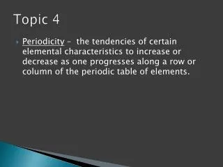
Rp dB IL dB 0dB -3dB Rejection BW -Ax dB fLx fLp fo fHp fUx Technical Parameters of Filter IL: RF insertion loss Rp: Ripple in the passband BW: Difference between upper and lower freqencies at which the attenuation is 3 dB SF: Describing the sharpness of the response with the ratio between the Ax dB and the 3 dB bandwiths Rejection: it is parameter according to the specification of a filter Qulity factor Q: Another parameter describing filter selectivity Q = f0 / BW
微波网络综合法设计滤波器 • 一般先设计低通原型滤波器,实际的低通高通带通带阻滤波器可由低通原型变换得到。 • 微波网络综合法设计滤波器时,将整个滤波器看成是多级二端口网络的级联,实际中这些二端口网络是串连电感并联电容。
微波网络综合法设计滤波器 • 由转移参量可以得到整个滤波器的频率响应特性。 S21= 2 / ( a + b + c + d ) 或 L = 10 log 1 / |S21|2 = 10 log |( a+b+c+d )/2|2 • 使频率响应满足指定的响应特性得到串连电感并联电容的大小。
典型滤波器响应 • 实际的滤波器响应有以下几种: 最大平坦响应(Butterwoth响应) 等波纹响应(Chebyshev响应) 椭圆函数响应 线性相位响应
典型滤波器响应 最大平坦响应(butterwoth响应) L = 1 + k2 ( ω/ωc )2N 式中N是滤波器阶数, ωc是截止频率,通带为(0, ωc ),通带边缘损耗为 1 + k2,常选为-3 dB,故 k=1。带外衰减随频率增加而单调增加, ω>>ωc时, L ≈( ω/ωc )2N, 所以衰减以每10倍频 20N dB的速率上升。
典型滤波器响应 等波纹响应(Chebyshev响应) L = 1 + k2 [ TN( ω/ωc ) ]2 式中TN(x)是Chebyshev函数,其多项式表示为 T1(x) =x T2(x) =2x2-1 T3(x) =4x3-3x T4(x) =8x4- 8x2+1 • • • 因为x<1时, |TN(x)|<1故通带内波纹为 1 + k2,常选为-3 dB,故 k=1。带外衰减随频率增加而单调增加, ω>>ωc时, 由TN(x)函数性质得到 L ≈ k2/4( 2ω/ωc )2N, 所以衰减也以每10倍频 20N dB的速率上升。但其衰减比最平坦响应大 22N/4
Comparison between Butterworht and Chebyshev Filters where B(3, ): attennuation response of 3-order butterworth-type T( 0.25, 3, ) ): attennuation response of 3-order chebyshev-type with ripple of 0.25dB T( 0.5, 5, ) ): attennuation response of 5-order chebyshev-type with ripple of 0.5dB T(1, 7, ) ): attennuation response of 7-order chebyshev-type with ripple of 1dB Comparison of Frequency response between Butterworht and Chebyshev Filters
典型滤波器响应 椭圆滤波器(elliptic filter)是利用椭圆函数(elliptic function)的双周期函数性质设计的。 就低通滤波器而言,如将巴特沃思滤波器与切比雪夫滤波器的幅频特性加以比较,它们具有以下特点: ①在巴特沃思滤波器中,无论是通带还是阻带均表现为单调衰减,并且不产生波纹; ②在切比雪夫滤波器中,通带内产生波纹,但阻带则为单调衰减; ③切比雪夫滤波器的截止特性比巴特沃思滤波器更为陡峭。 因而可以这样设想,如果在通带和阻带两方面都允许波纹存在,就能得到截止特性比切比雪夫滤波器更为陡峭的滤波器。基于这种思路的滤波器,就是由W.Cauer提出的椭圆滤波器。
椭圆函数滤波器的衰减特性为: 其中, 为 的分式有理多项式,其零点全部在通带 <1内,极点全部落在阻带 >1内,具有如下形式 其中 为零衰减频率, 为无穷衰减频率,零衰减频率的个数与 无穷衰减频率的个数相等。 典型滤波器响应 这种衰减特性与契比雪夫滤波器衰减特性相比,有如下特点: (1)通带内仍有契比雪夫滤波器响应的等波纹特性; (2)阻带内增加了有限频率上的极点,也呈现等波纹特性;(3)过渡段区域的斜率更为陡峭。
典型滤波器响应 线性相位响应 Φ(ω)= A ω[ 1 + p (ω/ωc )2N] 式中Φ(ω)滤波器电压转移函数的相位,p为常数。 通常良好的截止响应特性与良好的相位响应是一对矛盾。 还可以有其他的响应,上述4种是最常用的。
L 1 C ~ R 低通原型滤波器器件参数的确定 低通原型滤波器器件参数的确定是一个道理简单计算复杂的过程。在低通原型滤波器中,一般取g0=1, ωc=1。 对于N=2的低通原型,其结构图如右图所示: 由微波网络级联可得此电路的响应为L=1+[(1-R)2+(C2R2+ L2- 2LCR2)ω2 +L2C2R2ω4]/4R 最平坦响应为 L=1+ k2ω4 k=1 ω=1时衰减3dB得到 R=1, L = C = 21/2 等波纹响应为 L=1+ k2(2ω2-1)2 k=1 波纹3dB得到 R=5.81, L=3.1 C = 0.53
shunt capacitance series inductance L2=g2 Ln=gn rG=g0=1 rL=gN+1=1 ~ C1=g1 C3=g3 L1=g1 L3=g3 rG=g0=1 series inductance shunt capacitance C2=g2 Cn=gn ~ rL=gN+1=1 低通原型滤波器器件参数的确定 一般低通原型滤波器的两种结构如下图所示。 图中器件的编号从信号源端的g0一直到负载端的gN+1. 两个电路同一编号的器件取值相同,给出同样的频响。因此它们互为对偶电路。
低通原型滤波器器件参数的确定 原则上,可求任意N阶低通原型滤波器的器件参数值。但工程应用时,N过大不实际。对于最平坦响应的低通原型滤波器。前人将至10阶滤波器的参数值列表如下:
低通原型滤波器器件参数的确定 最平坦响应的低通原型滤波器至15阶时的衰减曲线如下:
低通原型滤波器器件参数的确定 对于等波纹响应的低通原型滤波器,至10阶的滤波器参数值列表如下(带内波纹0.01dB):
低通原型滤波器器件参数的确定 等波纹响应的低通原型滤波器至15阶时的衰减曲线如下:
n g g g g g g g g g g g 1 2 3 4 5 6 7 8 9 10 11 1 2.000 1.0000 2 1.5774 0.4226 1.0000 3 1.255 0.5528 0.1922 1.0000 4 1.0598 0.5116 0.3181 0.1104 1.0000 5 0.9303 0.4577 0.3312 .2090 0.0718 1.0000 6 0.8377 0.4116 0.3158 6 .2364 .1480 0.0505 1.00 7 0.7677 0.3744 0.2944 .2378 .1778 .1104 0.0375 1.0000 8 0.7125 .3446 0.2735 .2297 .1867 .1387 .0855 0.0289 1.000 9 0.6678 0.3203 0.2547 .2184 .1859 .1506 .1111 0.0682 0.0230 1.0000 10 0.6305 0.3002 0.2384 2 .2066 .1808 .15390 .1240 0.0911 0.0557 0.0187 1.0000 低通原型滤波器器件参数的确定 对于线性相位响应低通原型滤波器,因为转移参量的相位不像幅度那样有较简单的表达式,器件参数求解更复杂。至10阶的滤波器参数值列表如下:
低通原型滤波器器件参数的确定 最大平坦响应和等波纹响应低通原型滤波器经常用到。有时通过查衰减曲线及查表得不到相应的阶数及器件参数值,这时可依据滤波器相关指标,由公式计算得到N及gn
ButterworthLowPass Filters1 Step1:Specification Impedance: Zo (ohm) Cutoff Frequency: fc (Hz) Stopband Frequency: fx (Hz) Maximum Attenuation at cutoff frequency: Ap (dB) Minimum Attenuation at stopband frequency:Ax(dB) Step 2: Determine the Number of elements,N is a integer Step 3: Calculate Prototype Element Values,gK。
é ù - 2 1 Mag ê ú arccos 2 2 Mag e ê ú × ë û ³ N f x arccos( ) f c ì ü é ù 1 1 - a = 1 cosh cosh í ý ê ú e N ë û î þ a 2 A - p ( 2 K 1 ) = 1 = = g A sin , K 1 , 2 ,..., N K 1 g 2 N a 2 4 A A p K = - é b ù rp 1 K K g = g + 2 2 B sin ( ) b = g = ln coth sinh K ê ú K g B N × 17 . 37 ë û 2 N - - 1 1 K K Chebyshev LowPass Filters2 Step1:Specification Impedance: Zo (ohm) Cutoff Frequency: fc (Hz) Stopband Frequency: fx (Hz) Maximum Attenuation at cutoff frequency: Ap (dB) Minimum Attenuation at stopband frequency:Ax(dB) Step 2: Determine the Number of elements,N is an odd integer that is to avoid differrence between the input and output impedance Step 3: Calculate Prototype Element Values,gK。 gN+1=1 N奇数 gN+1=coth2(β/4) N偶数
a)电容输入 b)电感输入 由滤波器的设计指标LAs(dB), 和LAr(dB),得到上述原型电路的系数,需要用雅可比椭圆函数的保角变换技术,其数学推导和计算都比较繁琐。现已有图标曲线,可供设计此类滤波器时查用。 L2 L4 L1 L3 L5 L2 L4 C2 C4 C1 C3 C5 C1 C2 LAs (dB) C1 C2 L2 C3 C4 L4 C5 1.309 35 0.977 0.2300 1.139 1.488 0.742 0.704 0.701 1.414 40 1.010 0.1770 1.193 1.586 0.530 0.875 0.766 1.540 45 1.032 0.1400 1.228 1.657 0.401 0.964 0.836 1.690 50 1.044 0.1178 1.180 1.726 0.283 1.100 0.885 L1 L2 C2 L3 L4 C4 L5 椭圆函数滤波器低通原型 两种椭圆函数低通滤波器原型电路 下表给出了N=5 带内波纹衰减Lar=0.1的椭圆函数低通滤波器的系数
0 :阻带抑制频率 :通带截止频率 椭圆函数滤波器技术参数 LAs:阻带抑制 LAr:通带波纹
C L BW BW 2 2 w w 1 L BW C L o o L 2 w BW L o L=gk 1 BW L 1 1 BW C C C BW C=gK BW 2 w C o 2 = - w = BW w w w w o U U L L w w w w c c c c Frequency transformations from normalized LPFto others Lowpass lowpass highpass bandpass bandstop Prototype pratical pratical pratical pratical Value value value value value
g1 g2 g3 g4 g5 2.2072 1.1279 3.1025 1.1279 2.2072 C1 L2 C3 L4 C5 Cal. value 93.658pF 119.67nH 131.65pF 119.67nH 93.658pF Practical 94pF 120nH 132pF 120nH 94pF Examples of LPF design Design a LC 1 dB ripple Chebyshev-type LPF(Zo=50 ohm) with 75MHz cutoff frequency and at least 20dB attenuation at 100MHz Solution: Step1:Specification Impedance: Zo (ohm)=50 Cutoff Frequency: fc (MHz)=75 Stopband Frequency: fx (MHz)=100 Maximum Attenuation at cutoff frequency: 3 (dB) Minimum Attenuation at stopband frequency:20(dB) Step 2: Determine the Number of elements N=5 Step 3: Calculate Prototype Element Values,gK。 Step 4:Select shunt capacitance series inductance
é ù - 2 1 Mag ê ú arccos e 2 2 Mag ê ú × ë û ³ N w arccos( ) X Design of BandPass Filters Step1:Specification Impedance: Zo (ohm) upper passband edge frequency: fPU (Hz) lower passband edge frequency: fPL (Hz) upper stopband edge frequency: fXU (Hz) lower stopband edge frequency: fXL (Hz) Maximum Attenuation at passband: Ap (dB) Minimum Attenuation at stopband:Ax(dB) Step 2: Determine the Number of elements,N is an odd integer that is to avoid differrence between the input and output impedance (1)For Butterworth Type (2)For Chebyshev Type
prototype bandpass Transforma-tion fomula Cp Lp Cp Cs Ls Ls Design of BandPass Filters2 Step 3: Calculate Prototype Element Values,gK,as before. Select series induct-ance shunt capacitance or shunt capacitance series inductance, then calculate the values of C and L 。 a) series inductance shunt capacitance b) shunt capacitance series inductance Step 4: Calculate the component values of bpf。Transformate the lowpass prototype element values to the bandpass ones according the right transformation table
é ù - 2 1 Mag ê ú arccos e 2 2 Mag × ê ú ë û ³ N w arccos( ) X æ ö 2 f 1 æ ö 2 f 1 ç w = - = f o 2 . 778 ç w = - = o f 3 . 333 , ç ç X 2 XU f BW X 1 XL è ø f BW è ø XU Pass XL Pass = - = = × = BW f f 10 MHz f f f 74 . 83 MHz , pass PU PL o PL PU w = w w = MIN ( , ) 2 . 778 X X 1 X 2 Example of BPFdesign Design a 0.1 dB ripple Chebyshev-type BPF(Zo=50 ohm) with bandpass of 10MHz and central frequency at 75MHz, the Minimum Attenuation at stopband has to be 30dB with 30MHz stopband Step1:Specification Impedance): Zo = 50 ohm upper passband edge frequency: fPU = 75 + 5 = 80 MHz lower passband edge frequency: fPL = 75 – 5 = 70 MHz upper stopband edge frequency: fXU = 75 + 15 = 90 MHz lower stopband edge frequency : fXL = 75 –15 = 60 MHz Maximum Attenuation at passband: rp = 0.1 dB Minimum Attenuation at stopband:Ax = 30dB Step 2:determine the order of elements,N=3
rG=g0=1 L2=1.5937 rL=gN+1=1 ~ C1=1.4329 C3=1.4329 C1 456pF L2 1268nH C3 456pF Transformated values of BPF L1 10nH C2 3.6pF L3 10nH Result Step 3: Calculate Prototype Element Values,gK. Select shunt capacitance series inductance type. Calculate the values of L and C Step 4: Calculate the component values of bpf according the transformation table。
Home work 1) Design a 0.5 dB ripple Chebyshev-type LPF(Zo=50 ohm) with bandpass of 10MHz and central frequency at 75MHz, the Minimum Attenuation at stopband has to be 20dB with 30MHz stopband, design a Butterworth-type LPF with the same specification and do comparison between them 2) Design a LC 0.1 dB ripple elliptic functionLPF(Zo=50 ohm) with 75MHz cutoff frequency and at least 35dB attenuation at 98MHz. and calculate its frequency responding curve by using ABCD matrix