Download
1 / 2
20 likes | 102 Views
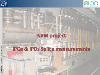
QPS for IPQs, IPDs and Inner Triplets. Preparation, IST and Hardware Commissioning 2009.

E N D
QPS for IPQs, IPDs and Inner Triplets. Preparation, IST and Hardware Commissioning 2009 • The DQGPUs (types B1, B2 and C) are presently being modified by QPS to separatethe powering of the redundant Detector Boards between UPS1 (F3) and the new UPS2 (F4). Modifications are on the CRATE LEVEL, not on the board level. • Modification of the Protection Crates for the IPDs and IPQs in sector 23 (UA27) has been COMPLETED. QPS Lab tests are on-going. The units will be ready for insertion later this week. • The QPS Lab tests include verification of communication and the protection features in case of a loss of any of the two UPS grids. The 100 ms, 50% UPS voltage window is assured due to the power supply input voltage tolerance, but checked. • Lab tests also comprise verification of Detection Threshold and Discrimination Window in Simulation Mode • IST comprises: - Communication tests - Resistance measurements of magnet heater circuits - Discharge tests at Zero DC current with firing of all heaters. Verification of voltage decays. Comparison with previously recorded profiles - Verification of voltage tap integrity, incl. those for the Leads Protection • During HWC: • Interlock testing without firing of heaters. • Measurement of input voltages U1, U2 and Ures during powering. PM and Logging checks. • No request from QPS for real quench tests as threshold and discrimination window is • checked in simulation mode K.Dahlerup-Petersen - MP3 - 2 June 2009
Request for an Early Powering Test of the RB Circuit in S23 • The first and only occasion to obtain an early test of the prototype nQPS CRATE, mounted with the prototype cards for local busbar protection (DQQBS), the SymQ cards (DQQDS) and the DQAMG-type S acquisition controller board. • Occasion to measure, for the first time, the voltage signals across individual busbar segments as well as the associated dipole voltages for inductive compensation. First attempt to correct the compensation. • Occasion to measure, for the first time, the total dipole voltage with current in the circuit. High precision measurements with the DQQBS card. Intended for possible replacement of the Snapshot method, as no ‘internal’ splices are absent in this absolute resistance determination. • First occasion to measure the electrical noise levels with DC current in the Powering Circuit. • Early possibility to verify the communication through the new WorldFip links of the nQPS crate. • First possibility to verify in-situ the algorithms for the 4-dipole comparison of the Aperture-Symmetric Quench Scheme. • First occasion to measure the current decay time constant with the new Extraction Resistor configuration (225 mOhm in stead of 150 mOhm) – 68 s time constant instead of 04 s. • Requested parameters: Measuring plateau's at 400 A, 600 A, 800 A and 1’000 A. dI/dt of 2-3 A/s. Cryo at 1.9 K. HWC done up to 1 kA. Plateau duration 10 min. Opening of the Extraction Switches after 10 min at 1’000 A. K.Dahlerup-Petersen - MP3 - 2 June 2009