Download
1 / 38
510 likes | 933 Views
Chapter 3 Resistance. ECET 1010 Fundamentals. 3.1 Resistance. Opposing force – due to collisions between electrons and between electrons and other atoms Converts electrical energy into another form of energy such as heat. Resistance. Determined by the following four factors Material Length

E N D
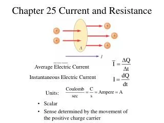
Chapter 3Resistance ECET 1010 Fundamentals
3.1 Resistance • Opposing force – due to collisions between electrons and between electrons and other atoms • Converts electrical energy into another form of energy such as heat
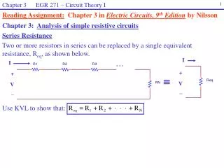
Resistance • Determined by the following four factors • Material • Length • Cross-sectional area • Temperature • R = ρ l / A
3.2 Resistance: Circular Wires • The higher the resistivity, the more the resistance • The longer the length of the conductor, the more the resistance • The smaller the area of the conductor, the more the resistance • The higher the temperature of the conductor, the more the resistance
Area of Circular Wires • The area of the conductor is measured in circular mils (CM) • 1 mil is one one-thousandth of an inch • A wire with a diameter of 1 mil has an area of 1 circular mil (CM) • Area of Circle = π r2 = π d2 / 4
Area of Circular Wires • Relationship between circular mils (CM) and square mils • 1 CM = π / 4 sq. mils • Relationship between area in circular mils (CM) and diameter in mils • ACM = (dmils)2
Example 3.1 What is the resistance of a 100-ft length of copper wire with a diameter of 0.020 in. at 20°C? l = 100 ft ρ = 10.37 CM-Ω/ft (Table 3.1) d = 0.020 in = 20 mils A = d2 CM = 400 CM R = 10.37 * 100 / 400 = 2.59 Ω
Example 3.2 You have been given a carton of wire where an undetermined number of feet of the wire has been used. Find the length of the remaining copper wire if it has a diameter of 1/16 in. and a resistance of 0.5 Ω. ρ = 10.37 CM-Ω/ft d = 1/16 in = 62.5 mils A = (62.5)2 CM = 3906.25 CM R = 0.5 Ω l = 3906.25 * 0.5 / 10.37 = 188.34 ft
Example 3.3 What is the resistance of a copper bus-bar (as used in the power distribution panel of a high-rise office building) 3 ft long, 5 in. wide, and 0.5 in. thick? l = 3 ft ρ = 10.37 CM-Ω/ft A = ½ in * 5 in = 500 mil * 5,000 mil = 2.5 * 106 mil2 ACM = 2.5 * 106 * (4/ π) = 3.183 * 106 CM R = 10.37 * 3 / 3.183 * 106 = 9.773 * 10-6 Ω
3.3 Wire Tables • Standardize the size of wire produced by manufacturers throughout the United States • See Table 3.2 – American Wire Gage (AWG) sizes • AWG number • Area in circular mils • Resistance in Ω per 1,000 feet at 20°C • Maximum allowable current
Example 3.4 Find the resistance of 650 ft of #8 copper wire (T = 20°C). from Table 3.2 0.6282 Ω / 1,000 ft R = 650 ft * (0.6282 Ω / 1,000 ft) = 0.408 Ω
Example 3.5 What is the diameter, in inches, of #12 copper wire? from Table 3.2 ACM = 6529 CM = (dmils)2 d = 80.8 mil = 0.0808 in ~ 1/12 in
Example 3.6 For the following system, the total resistance of each power line cannot be more than 0.025 Ω, and the maximum current to be drawn by the load is 95 A. What gage wire should be used? Need a picture of an input connected to a load by two 100 ft lengths of solid round copper.
Example 3.6 (continued) From Table 3.2 we choose #3 wire since its maximum allowable current is 100 A and this is greater than 95 A We need to check and make sure 100 ft of #3 wire is NOT more than 0.025 Ω R = 100 ft * (0.1970 Ω / 1,000 ft) = 0.01970 Ω ‹ 0.025 Ω
3.5 Temperature Effects • Temperature has a significant effect on the resistance of • Conductors • Semiconductors • Insulators
Conductors • For good conductors, an increase in temperature will result in an increase in the resistance level (due to an increase in the random motion of the particles in the material). Consequently, conductors have a positive temperature coefficient.
Semiconductors • For semiconductor materials, an increase in temperature will result in a decrease in the resistance level (due to an increase in free carriers). Consequently, semiconductors have a negative temperature coefficient.
Insulators • As with semiconductors, an increase in temperature will result in a decrease in the resistance of an insulator. The result is a negative temperature coefficient.
Inferred Absolute Temperature • Effect of temperature on the resistance of copper • R1,t1 and R2,t2 • -234.5 °C • Similar triangles yield (234.5 + t1) / R1 = (234.5 + t2) / R2 • Adapting to any material( |T| + t1) / R1 = ( |T| + t2) / R2
Example 3.9 If the resistance of copper wire is 50 Ω at 20° C, what is its resistance at 100° C (boiling point of water)? (234.5 + 20) / 50 Ω = (234.5 + 100) / R R = 65.72 Ω
Example 3.10 If the resistance of copper wire at freezing (0° C) is 30 Ω, what is its resistance at -40° C? (234.5 + 0) / 30 Ω = (234.5 - 40) / R R = 24.88 Ω
Example 3.11 If the resistance of an aluminum wire at room temperature (20° C) is 100 mΩ (measured by a milliohmeter), at what temperature will its resistance increase to 120 mΩ? (236 + 20) / 100 mΩ = (236 + t) / 120 mΩ t = 71.2° C
Temperature Coefficient of Resistance • Definition of temperature coefficient of resistance at 20° C. • α20 = 1 / (|T| + 20° C) • For copper, α20 = 0.00393Ω/° C/Ω • The higher the temperature coefficient of resistance for a material, the more sensitive the resistance level to changes in temperature.
Temperature Coefficient of Resistance • Resistance R at a temperature t given by: • R = R20 [1 + α20(t - 20° C)] • Which can be written as: • R = ρ (l/A) [1 + α20(ΔT)]
Example If the nominal resistance of a copper wire is 5 Ω, what will its resistance be at 30 ° C? R = 5 Ω [1 + 0.00393(30° C - 20° C)] R = 5 Ω (1.0393) = 5.1965 Ω
PPM/°C • Parts per million per degree Celsius • For resistors • 5000-PPM is high • 20-PPM is low • 1000-PPM/°C says a 1° C change in temperature gives a change in resistance equal to 1000 parts per million or 1,000/1,000,1000 or 1/1,000 of its value. ΔR = (Rnominal/106) (PPM) (ΔT)
Example 3.12 For a 1-kΩ carbon composition resistor with a PPM of 2500, determine the resistance at 60°C. Rnominal = 1,000 Ω PPM = 2,500 ΔT = t – 20° C = 60° C – 20° C = 40° C ΔR = (1,000/106) (2,500) (40) = 100 Ω R = Rnominal + ΔR = 1,100 Ω
3.8 Color Coding and Standard Resistor Values • See Table 3.7 • Way to identify • Resistance • Tolerance • Reliability
Bands • First and second band give first two digits • Third band gives power-of-ten multiplier • Fourth band gives tolerance, ±percent • Fifth band gives reliability, failures per 1,000 hours use • See Table 3.8 for standard resistor values
Example 3.13a Find the range in which a resistor having the following color bands must exist to satisfy the manufacturer’s tolerance: Gray, Red, Black, Gold, Brown 8 2 0 5% 1% 82 * 100± 5% Ω 77.9 – 86.1 Ω
Example 3.13b Find the range in which a resistor having the following color bands must exist to satisfy the manufacturer’s tolerance: Orange, White, Gold, Silver, No Color 3 9 -1 10% 39 * 10-1± 10% Ω 3.51 – 4.29 Ω
Conductance • Reciprocal of resistance G = 1 / R (Siemens, S) • As a function of area, length, and resistivity G = A / (ρl)
Example 3.14 What is the relative increase or decrease in conductivity of a conductor if the area is reduced by 30% and the length is increased by 40%? (The resistivity is fixed.) Gi = Ai / (ρili) Gr = Ar / (ρrlr) = 0.7 Ai / (ρi (1.4) li) = (0.7/1.4) Ai / (ρili) = 0.5 Gi