Download
1 / 38
460 likes | 777 Views
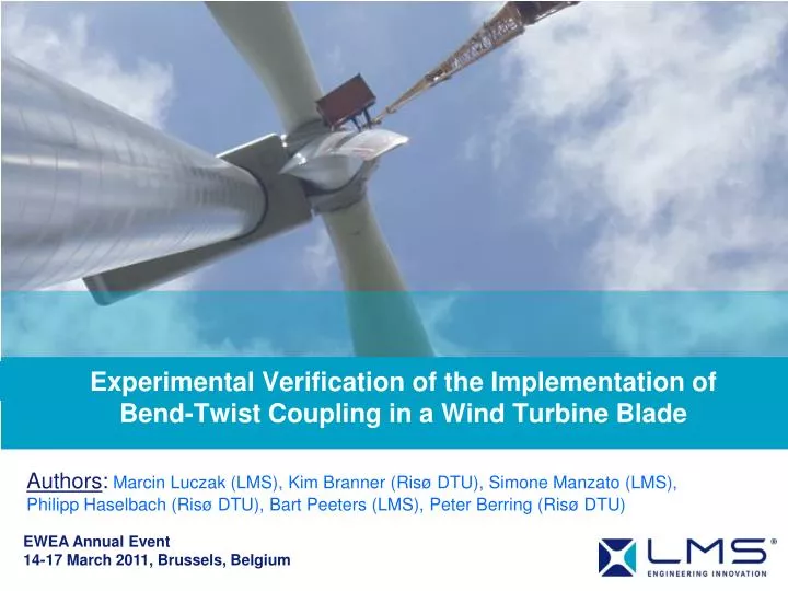
Experimental Verification of the Implementation of Bend-Twist Coupling in a Wind Turbine Blade. Authors : Marcin Luczak (LMS), Kim Branner ( Risø DTU ), Simone Manzato (LMS), Philipp Haselbach (Risø DTU), Bart Peeters (LMS), Peter Berring (Risø DTU). EWEA Annual Event

E N D
Experimental Verification of the Implementation of Bend-Twist Coupling in a Wind Turbine Blade Authors: Marcin Luczak (LMS), Kim Branner (Risø DTU), Simone Manzato (LMS), Philipp Haselbach (Risø DTU), Bart Peeters (LMS),Peter Berring (Risø DTU) EWEA Annual Event 14-17 March 2011, Brussels, Belgium
Outline • Introduction • Goal and scope of the investigation • Object of an investigation • Static investigations • Dynamic investigations • Assessment • Conclusions and further research • Acknowledgements
1 Introduction
Introduction • Passive blade load reduction • sudden wind changes, • anisotropic compositematerial can introduce the bend-twist coupling • aero-elastic tailoring of the blades • extend the fatigue life
2 Goal and scope
Objective Main goal : experimentally confirm the numerical prediction of modification of the dynamic and static properties of the original and modifiedwind turbine blade. SCOPE:
3 Object
Object: original composite material wind turbine blade • Blade section provided byVestas Wind Systems A/S. • 8m section was selected from the 23m blade. The 8mblade section goes approximately from R11m to R19m
Object: modified wind turbine blade section • Blade modification • Introduction of bend-twist coupling into 8 meter blade section Extra UD lamination
4 Static investigations
Static ExperimentsTest rig & setup: static boundary conditions and load configurations • 2 “clamps” in the wide end, which gives the clamped boundary • Max horizontal force of 500 kN and moment of 50 kNm. Bending flapwise Bending edgewise Pure torsion
Static ExperimentsTest rig & setup: static measurement techniques • ARAMIS system camera setup and measuring pattern
Bend and twist definition LENGTH OF THE BLADE Bend Angle
Bend and twist definition ORIGINAL MODIFIED Twist Angle Twist Angle
Static Results - TESTOriginal and modified blade section static measurement • Flapwise bending load Bend Twist The z-rotationfor the original blade section is almost equal to zero The z-rotation for themodified blade section indicates that the section now has a measurable bend-twist coupling
5 Dynamic investigations
Dynamic TEST and FEM Results– original blade section1stflap bending mode @ 4.47 Hz • Bend and Twis angles for FEM and test were estimated • Good consistency of natural frequencies MSc Thesis Mark Capellaro 2007
Dynamic ExperimentsTest rig & setup: dynamic boundary conditions & exctitation • 2 “clamps” in the wide end, which gives the clamped boundary • Blade excited by 2 electromagneticshakers in normal direction • Burst random excitation
Dynamic ExperimentsTest rig & setup: modified blade section geometry 1 • 1st set of measurement performed on 25 sections along pitch axis (every 250 mm) • 5 points measured on each section • X and Y acceleration measured, with respect to the blade surface orientation 1=> Trailing edge 3 => Max height 5 => Leading edge 2-4 => Mid points 4 5 3 2 ORIENTATIONS: X => NORMAL TO BLADE SURFACE Y => TANGENT TO BLADE SURFACE Y X Z
Dynamic ExperimentsTest rig & setup: geometry • Support structure, XYZ direction accelerations measured M2R M1R C2U C1C2R C1U M2L M1L C1C2L C2D ST C1D
Dynamic ExperimentsTest rig & setup: geometry • Measurement points • 130 measurement points + 2 driving points
Dynamic ResultsLinearity, reciprocity & coherence for modified blade section Linearity Reciprocity • Linearity & reciprocity check to verify if the structure meets the modal analysis assumptions Coherence
DynamicResultsLinearity, reciprocity & coherence Modal synthesis AutoMAC: blade AutoMAC: blade+support • PolyMAX modal parameter estimation • Good modal synthesis • Well-separated modes
DynamicResults – modified blade section1st flap bending mode @ 4.48 Hz
DynamicResults – modified blade section1st edge bending mode @ 12.08 Hz
DynamicResults – modified blade section2ndflap bending mode @ 19.24 Hz
Dynamic Results – modified blade section1sttorsion mode @ 40.92 Hz
6 Assessment
Correlation analysis FEM model – TEST modelFinite Element Method model of modified blade section • FEM and Test geometries correlated and the FE nodes are paired with measurement points
Correlation analysis FEM model – TEST modelFinite Element Method model of modified blade section • Comparison of the natural frequencies for the experimental and numerical results obtained for the original and modified blade • Modal Assurance Criterion matrix for test and simulation modal vectors of modified blade
Numerical and experimental twist and bend angles1st flap bending mode original and modified blade section Original blade - Finite Element Modified blade - Finite Element Original blade - Test Modified blade - Test
Numerical and experimental twist and bend angles2nd flap bending mode original and modified blade section Original blade - Finite Element Modified blade - Finite Element Original blade - Test Modified blade - Test
Bend-twist coupling index for 1st and 2nd flapwise mode • For each considered blade cross-section, the ratio between the computed relative twisting and bending angles is evaluated. • Coupling index value close to zero means that the twisting is negligible with respect to the bending for the considered mode • High coupling index value means that twisting is dominant. • Coupling index value close to one, means twisting and bending are of the same order of magnitude
7 Conclusions & further research
Conclusions • Multidisciplinary and interdisciplinary research oriented for the experimental and numerical study in static and dynamic domains on the bend-twist coupling in the original and modifiedfull scale section of the wind turbine blade structure • Good correspondance between modal models (natural frequencies, damping ratios & mode shapes) in frequency range 0 - 100 Hz • Support structure influence on the FE-Test correlation is significant • Introduction of the bend-twist coupling was confirmed in static and dynamic experiments and simulations • Next step – Fluid-Structure Interaction model incorporating Computational Fluid Dynamics
8 Acknowledgements
Acknowledgements Vestas Wind Systems A/S has provided and modified the blade sections presented in this study. The work is partly supported by the Danish Energy Authority through the 2007 Energy Research Programme (EFP 2007). The supported EFP-project is titled “Anisotropic beam model for analysis and design of passive controlled wind turbine blades” and has journal no. 33033-0075. The support is gratefully acknowledged and highly appreciated. Research presented in section 5 was conducted in the context of the FP7 project PROND Ref No. 239191. Computations were performed on a 50Tflop cluster in TASK Academic Computer Centre in Gdansk, Poland.