Download
1 / 53
540 likes | 705 Views
Automated Machining. Manufacturing Processes. Outline. Machining Centers Equipment Tool Changers Centering and Clamping Selection of Equipment Selection of Tooling Machine Performance Monitoring Manufacturing Cells Manufacturing Economics. Machining Centers. Machining Center

E N D
AutomatedMachining Manufacturing Processes
Outline • Machining Centers • Equipment • Tool Changers • Centering and Clamping • Selection of Equipment • Selection of Tooling • Machine Performance Monitoring • Manufacturing Cells • Manufacturing Economics
Machining Centers Machining Center A computer-controlled machine tool capable of many types of cutting operations on multiple surfaces and directions on a workpiece
Manufacturing Centers Z Y X 3-Axis Operation φ 4-Axis Operation φ θ 5-Axis Operation
Example of a Machining Center Example of a 5-axis CNC machine (the tool pivots instead of the workpiece)
Equipment Pallets The workpiece is placed on a pallet (module) which can be oriented in different directions by the machine Automatic Pallet Changers When the workpiece is finished, automatic pallet changers remove it and replace it with another workpiece
Pallets Example of a part mounted on a pallet Courtesy Toth Industries
Equipment Automatic Tool Changer Can switch between up to 200 tools stored in a magazine, drum, or chain Tool Exchange Arm Picks up particular tools with attached toolholders
Tool ChangerTypes Automatic (Sequential) Spindle Turns one increment in one direction for each tool change; tools must be placed in the spindle in the order they are used Indexable (Random Access) Spindle Turns either direction to make a specific tool accessible; tools can be placed in any order as long as the computer knows their positions
Tool ChangerTypes 2 3 1 4 6 5 Sequential Spindle 8 1 4 6 2 5 3 7 Random Access Spindle
Tool Changer Spindle Tool changer spindle capable of holding 60 tools Courtesy of Toth Industries
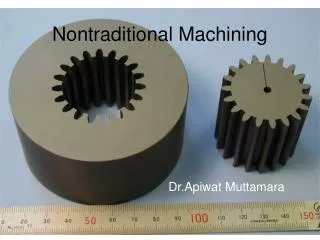
Types ofManufacturing Cutting From Bulk Material Starting with a readily available shape (rods, ingots etc.) and machining the part from this Cutting From Near Net Shape Starting with a pre-formed (often cast) piece with the general shape of the part and removing little material
Centering andClamping Pre-cast designs should be made so that the machines can clamp and orient them quickly and accurately Parts to be lathed should have radially symmetrical outer surfaces and pre-cast holes to mark the center; they should also have a center of mass on the center line to prevent vibration
Orienting andClamping Pre-cast parts should have at least three distinct features that the computer can recognize and use to orient the part notches holes
Centering andClamping Pre-cast parts should have flat parallel surfaces for clamping or cylindrical surfaces for chucking Areas to be clamped or chucked can be ground flat after casting to improve grip
Selection ofEquipment Various types of parts may require various machining centers Parts with numerous cylindrical surfaces (or other radially symmetrical surfaces) should be mounted on a machine center capable of turning Specialized machine centers are available for high-speed machining and for ultraprecision cutting
Selection ofEquipment Example: Pump Cover Starting with the rough casting, drill and ream the center hole, then cut the internal notch with a milling cutter. Mount the piece on a mandrel and use turning operations to cut the faces and outer edge. Mill the external notch and drill and ream the smaller holes in the plate.
Selectionof Tooling The proper selection of tools depends on the workpiece material, size and shape of holes, radii of the corners of milling pockets, and various other parameters The selection of tools affects the cost and time of the operation
Machine PerformanceMonitoring Y Y’ Part Orientation X’ X Cutting Performance
Machine PerformanceMonitoring Tool/Part-Checking Station Measures workpieces and tools so that the computer can compensate for variations and tool wear Touch Probes Pressed against a workpiece or tool to measure its exact size and position
Measurement andAdjustment Advanced machining software can use data from probes to adjust its coordinate system, ensuring that critical distances remain within tolerances even in deformed workpieces critical distances Holes to be drilled (initial) Holes to be drilled (adjusted)
Touch Probes tool holder probe part Using a touch probe to measure a part Courtesy Toth Industries
Touch Probes A machining center, being used to measure and determine the orientation of a part Courtesy of Toth Industries
Touch Probes tool changer arm probe part A machining center, being used to measure and determine the orientation of a part Courtesy of Toth Industries
Touch Probes To determine the orientation of the part, the machine measures the two large holes and calculates their centers. A line constructed between the centers serves as a base for the computer’s coordinate system. Courtesy of Toth Industries
Machine PerformanceMonitoring Tool Failure Detection: • Time When the total cutting time of the tool exceeds the pre-programmed tool life, the tool is replaced • Horsepower Dull tools draw more power; if the power exceeds pre-programmed limits, the tool is replaced
Machine PerformanceMonitoring Tool Failure Detection: • Acoustic Emissions Cutting tools produce ultrasonic vibrations and weakened ones produce up to five times the normal amplitude; when it rapidly increases, the tool is immediately replaced
Machine PerformanceMonitoring Tool Failure Detection: • Feed Force Records the feed force of sharp tools; if the force increase exceeds a predetermined percentage, the tool is replaced; if the force suddenly rises, the tool has broken and is replaced immediately
Manufacturing Cells –Examples Courtesy of Toth Industries
ManufacturingEconomics Cost: If the cutting speed is too low, the cost of cutting increases because of increased power consumption If the cutting speed is too high, the cost of tool replacement increases because tools wear out faster
ManufacturingEconomics Time: If the cutting speed is too low, the cutting time increases If the cutting speed is too high, the tool replacement time increases