Download
1 / 64
1.58k likes | 2.9k Views
Lecture 3 Control valves. Elements of the final control. Automatic Valve actuator. I/P transducer. Valve body. Current Signal 4-20 ma. Flapper. Nozzle. Back pressure. Pneumatic Signal 3-15 psi. Diaphragm control valves. Globe valve. Rotary valve. Rotary valve. Globe valve.

E N D
Lecture 3 Control valves
Elements of the final control Automatic Valve actuator I/P transducer Valve body
Current Signal 4-20 ma Flapper Nozzle Back pressure Pneumatic Signal 3-15 psi
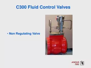
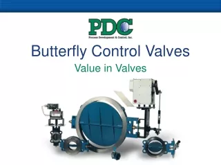
Globe valve Most common control valve style Can be single- or double- seated
Single-seated valves • Usually are employed when • Tight shut-off is required, • In sizes of 1 inch or smaller where unbalance forces acting on the valve stem is unimportant. • Usually have a top guided construction
Double-seated valves • Usually is top and bottom guided. • Practical leakage approaches 0.5% of the rated CV. • Advantage lies in reduction of required actuator forces. • Have upper and lower ports of different diameters---allow to withdraw smaller plug through the larger port.
Angle valve • Single seated valves with special body configuration to suit specific piping or flow measurements. • May be used in case where the piping layout does not allow installing a globe valve.
Three way valves • A design extension of a typical double-seated valve. • Can be used for diverting service and for mixing service.
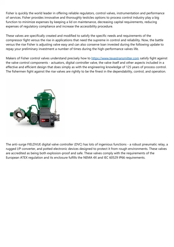
Actuators for control valves: • Pneumatically operated diaphragm actuators; • Piston actuators; • Electro-hydraulic actuators; • Electro-mechanical actuators; More than 90% in use are pneumatically operated piston or diaphragm type
Safety consideration • Air-to-open (AO) Failure close • Air-to-close (AC) Failure open
Defined at maximum Valve opening Related to valve inherent characteristics
Over sized plug to provide Additional Cv Special seat machined Into the body
Linear valves: A (X) =X= x/xo Equal percentage valves: A (X) = e -k(x/xo-1) = a-(X-1) Rangeability
What accomplishment a positioner can have? • Provide precise positioning of the valve • Provide adequate power on high-pressure applications • Increase control valve speed of response • Reverse valve action • Provide split range operation
Typical positioner performance • Pneumatic signal ranges: 3-9, 3-15, 9-15, 3-27, 6-30 psig • Air supply pressure: 20 to 100 psig • Repeatability: within 0.1% of stroke • Hysteresis: within 0.3% of stroke • Linearity: 0.5% of stroke
Control valve sizing Given expected pressure conditions, select throttling control valve to pass the required flow rate. It is a key step In ensuring that the process can be properly Controlled. Basic sizing practices have been standardized Upon (e.g., ISA S75.01) and are implemented as PC-based program by manufactures.