Download
1 / 15
150 likes | 248 Views
Simplified VO M&V Protocols Approved May 4 th , 2010. Simplified VO M&V Protocol can be applied to distribution systems with Residential and Small Commercial Loads to verify energy savings from reduced voltage operation.

E N D
Simplified VO M&V ProtocolsApproved May 4th, 2010 • Simplified VO M&V Protocol can be applied to distribution systems with Residential and Small Commercial Loads to verify energy savings from reduced voltage operation. • Protocol makes use of historical data, system modeling, 7-day M&V ‘on’ and 7-day ‘off’ hourly measurements, and “Deemed” end-use VO Factors determined from NEEA DEI Study 2007 results. • Protocol can be used with three Voltage Regulation Techniques, VFR, LDC, and AVFC. 1
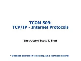
Volts 126 120 114 Feeder Length Three Voltage Regulation Techniques Existing Vset = 125V New Vset = 122V • Voltage Fixed Reduction (VFR) • Fixes the voltage level at the substation source and the voltage level at the end of the feeder varies with load • Old voltage setting Vset = 125V, R and X settings = 0 • New voltage setting Vset = 122V, R and X settings = 0 2
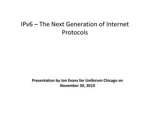
Volts 126 120 114 Feeder Length Three Voltage Regulation Techniques Existing Vset = 125V New Vset = 120V, R and X setting = 3 to 5 • Line Drop Compensation (LDC) • Fixes the voltage level at the end of the feeder and the voltage level varies at the substation source with load • Old voltage setting Vset = 125V, R and X settings = 0 • New voltage setting Vset = 120V, R and X settings = 3 to 5 3
Three Voltage Regulation Techniques • Automatic Voltage Feedback Control (AVFC) • Fixes the voltage level at the substation source based on real-time voltage feedback sign from the end of the feeder (s) 4
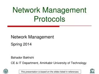
Volts 126 120 114 Feeder Length Three Voltage Regulation Techniques Existing Vset = 125V • Automatic Voltage Feedback Control (AVFC) • Fixes the voltage level at the substation source based on real-time voltage feedback sign from the end of the feeder • Old voltage setting Vset = 125V, R and X settings = 0 • New voltage setting Vset = 119V, R and X settings = 0 Vset = Adjusts for load conditions based on end of line feedback 5
Primary Voltage Zone Secondary Voltage Zone VCZ for LTC Transformer Feeder Load Tap Changer (LTC) Feeder Breaker Voltage Control Zones
VCZ for LTC VCZ for V-Reg Transformer Feeder V-Reg Load Tap Changer (LTC) Feeder Breaker Voltage Control Zones
Four Stages to Simplified VO M&V Protocol Historical Load Data: kWh-annual, Volt_Drop-max, kWpeak-demand Distr _Line Modeling Load_Flow Analysis Threshold Analysis Determine end-use VO Factor Estimate Potential Savings Install VO and SI Improvements 1. 2. 3. 4. Existing Performance Assessment and VO Implementation Plan System Improvements Baseline Pre-VO measurements 7-day measurements ‘OFF’ Veol, Vset, Esub Calculate Vpre-annual average VO Implementation Post-VO Measurements and Verification 7-day measurements ‘ON’ Veol, Vset, Esub Calculate Vpost-annual average Determine Verified Savings Persistence Measurements
Performance Thresholds • Power Factor • Power Factor on average > 98% (period) • Power Factor minimum > 96% (period) • Phase Unbalance • Must be < 0.15pu, or < 40 amps • Voltage Drop (Vd) for each voltage control zone • Must be < 3.3% on primary at feeder peak loads 9
Performance Thresholds (continued) • Maximum Voltage Drop Variance (Vdv) between feeders within the same voltage control zone (during period) • Must be < 0.25 p.u. or < 2.0V • Maximum Voltage Drop (Vd) for secondary • Must be < 4.0%, based on design standards and criteria • Voltage level must be > (114V+1/2 Bandwidth) and less than (126V-1/2 Bandwidth) 10
Why Performance Threshold are Critical Establishing thresholds helps to resolve key issue found in the pilot NEEA projects that did not perform well. • Reduces voltage fluctuation due to changing loads/conditions • Reduces losses in the distribution system • Allows recording periods to be minimized (1 week to establish daily load shapes and weekend/weekday load shapes) 11
395 VO Factor Determination • Uses Results from the NEEA DEI study to determine • Heating and cooling zones • Residential and commercial load • End-use load characteristics • Electric heating • Air conditioning 12
NEEA DEI Study VOf SensitivityMinor impacts due to AC End-Use Load 16% Variation
Voltage Reduction Calculation • Calculate ΔV for each voltage control zone • Dependant on which voltage control method • VFR Adjusted Average Voltage for VFR = [Regulator_Set_Point_Voltage_Setting – ½ * A * Annual_Load_Factor] • LDC/AVFC Adjusted Average Voltage for LDC = [Regulator_Set_Point_Voltage_Setting + Annual_Load_Factor *[B - 1/2 *A]] Where: A is the maximum voltage drop at peak load, and B is the Calculated Regulator Maximum Annual Volt-Rise 14
From NEEA’s DEI research and pilot VO calculation method already “approved” by RTF From proposed protocols Method of Calculating Energy Savings (Delta V) 15 Energy Saved = Change in voltage x Voltage Optimization Factor x Annual Energy + Energy Saved from System Improvements ESaved = ΔV x VOf x EAnnual +ΔESI • ΔV - determined from this program • VOf -derived from NEEA load research study and confirmed by EPRI studies, and other industry pilots and research • E Annual – Metered Data from Utility • ΔE - Energy Saved from System Improvements