Download
1 / 11
110 likes | 230 Views
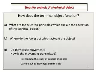
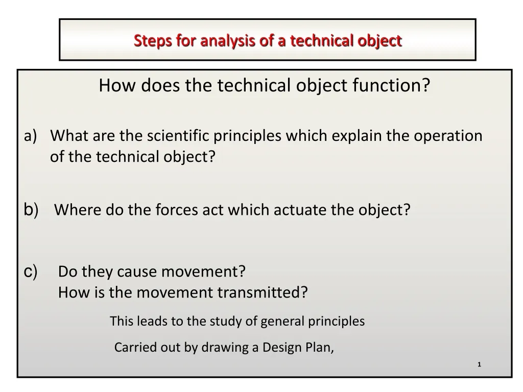
Steps for analysis of a technical object. How does the technical object function?. What are the scientific principles which explain the operation of the technical object?. b) Where do the forces act which actuate the object?. Do they cause movement? How is the movement transmitted?.

E N D
Steps for analysis of a technical object How does the technical object function? • What are the scientific principles which explain the operation of the technical object? b) Where do the forces act which actuate the object? • Do they cause movement? • How is the movement transmitted? This leads to the study of general principles Carried out by drawing a Design Plan, 1
Standardized symbols Design Plan The Design Plan is the simplified representation of a technical object It is used to explain the forces and movements which come into play in the operation of the technical object A Design Plan includes the following elements: 1. The parts represented in different colors. 2. The name of the parts (designation). 3. The movements carried out by the parts. 4. The forces in action. 5. Any guidance and links, (if necessary). 2
Standardized symbols Symbols of Movements and of Forces Unidirectional Translation Tension Bidirectional Translation Compression Unidirectional Rotation Torsion Bidirectional Rotation Shearing Rotation and Translation (helical) Page 9
Standardized Symbols Page 10
A Design Plan for a pair of scissors Free in rotation and fixed in translation Upper Blade F Shearing Paper F A Design Plan includes the following elements: A Design Plan includes the following elements: A Design Plan includes the following elements: 1. The parts represented in different colors. 1. The parts represented in different colors. 1. The parts represented in different colors. Pivot 2. The name of the parts (designation). 2. The name of the parts (designation). 2. The name of the parts (designation). F Lower blade 3. The movements carried out by the parts. 3. The movements carried out by the parts. 4. The forces in action. Bidirectional rotation 5. Any guidance and links, (if necessary). The Components (parts) Movements Forces 5
Step of analysis of technical objects How is the object constructed? a) What materials are the parts made of? b) Why do the parts have these forms? c) What role does each part play in the system ? (Simple and complex mechanical functions) • How are the parts linked together? • How is guidance provided? This leads to a study of construction. This is carried out by a technical diagram/construction diagram 6
Technical/Construction Diagram of a pair of scissors Upper handle Upper blade A Technical Diagram contains the following: A Technical Diagram contains the following: 1. The pieces making up the technical object: 1. The pieces making up the technical object: a. The materials used; a. The materials used; Pivot b. The shape of the components; Lower blade b. The shape of the components; c. Relative size of the components; c. Relative size of the components; d. The name of the components. Lower handle Legend of materials d. The name of the components. Steel 2. The role of the components: a. The links between the parts; Plastic b. The guidance between the parts. 7
Symboles normalisés Assisted Exercises: Your Turn Exercice 1: Staple Remover Top Lever Pivot Spring Bottom Lever 8 Original material created by Emmanuel Fournier
Assisted Exercises: Design Plan for a Staple Remover Technical Diagram of a Staple Remover Top Lever Protector Top Lever Torsion Spring Pivot Pivot A Technical Diagram contains the following: Torsion Spring A Design Plan includes the following elements: Protector 1. The pieces making up the technical object: Bottom Lever Bottom Lever 1. The parts represented in different colors. a. The materials used; Material Legend b. The shape of the components; 2. The name of the parts (designation). c. Relative size of the components; Steel 3. The movements carried out by the parts. d. The name of the components. Plastic 2. The role of the components: 4. The forces in action. a. The links between the parts; 5. Any guidance and links, (if necessary). b. The guidance between the parts. 9 Original material created by Emmanuel Fournier
Standard symbols Assisted Exercises: Exercise 2: C-Clamp 10 Original material created by Emmanuel Fournier
Assisted Exercises: Design Plan for a C-Clamp Technical Diagram for a C-Clamp Fixed Jaw Fixed Jaw Frame Moveable Jaw Frame Moveable Jaw Handle Handle Adjusting Screw Adjusting Screw F Materials Legend Steel Bottom View 11 Original material created by Emmanuel Fournier