Download
1 / 21
210 likes | 440 Views
Performance of Injection Protection Systems V.Kain AB/CO. Contents SPS Extraction – Transfer – LHC Injection Injection Protection System Principle Passive Protection Interlocking Simulations for Protection Level Conclusions.

E N D
Performance of Injection Protection SystemsV.Kain AB/CO • Contents • SPS Extraction – Transfer – LHC Injection • Injection Protection System Principle • Passive Protection • Interlocking • Simulations for Protection Level • Conclusions Input from B. Goddard, R. Genand, R. Schmidt,J. Wenninger, M. Werner Verena Kain, AB-CO
SPS Extraction – Transfer – LHC Injection Beam 2 Beam 1 Verena Kain, AB-CO
Extraction Transfer Injection Injection Process To define the Injection Protection System, SPS Extraction, Transfer and LHC Injection must be treated together. SPS: MSE…extraction septum MKE…extraction kicker LHC: MSI…injection septum MKI…injection kicker TED…beam stopper in transfer line TDI…injection stopper in injection region BEAM2: LSS4/TT40 – TI 8 – IR 8
Holes in Cu : 450 GeV p+ beam (from 2004 TT40 materials test) 8x10¹²p+= ¼ of full batch 5.3x10¹²p+= 1/6 of full batch Injection/Extraction Constraints Full nominal injected LHC batch: 3.3x10¹³p+, 450 GeV • Damage limit: ~2x10¹²p+, ~5 %of injected batch • Small Aperture: • 7.5s LHC aperture at 450GeV • Tight aperture in transfer line (MSI injection septum ~7s) Inside, damage visible over ~1m (melted steel) Verena Kain, AB-CO
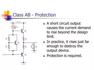
What can go wrong: magnet trips, kicker failures, wrong settings… 10 cm ~25cm long hole in QTRF chamber • Magnet trips can move trajectory by many s in short time (MSE extraction septum: 40s in 1ms) • Kicker erratics, missings, timing etc. • Operator error • Corrupted settings Extraction septum (MSE) trip during high intensity extraction, Oct 2004 Injection Process • Slow failures: • 10s in > 2-3ms: relying on interlocking • Fast failures: • 10s in < 2-3ms: interlocking + collimators • Ultra-fast failures: • 10s in few ms: collimators Verena Kain, AB-CO
Avoidance Procedures to avoid dangerous situations e.g. never inject high intensity beam in empty LHC Beam Presence Flag→ protects against many failures Principle of Machine Protection for Injection Process Protection ACTIVE HW surveillance: PCS, FCCM, settings monitoring, equipment status Master Extr./ Inj. BIC Inj./ Extr. Inhibit HW Local BIC Failure, Error effect on: PASSIVE Collimators, Absorbers Beam Verena Kain, AB-CO
Passive Protection for fast and ultra-fast failures • Protection of LHC aperture and MSI injection septum aperture: • TCDI collimatorsfor failures upstream of injection regions • “generic” protection system with full phase coverage • Dedicated collimators for kicker failures: • MKI (LHC) failure: TDI beam stopper + TCLI collimators are 90° downstream • MKE (SPS) failure: TPSG diluter is 90° downstream • No dedicated collimators for septum failures • Protection from MSE and MSI failures interlocking Verena Kain, AB-CO
TCDI Transfer Line Collimators • Close to LHC and injection septum (last 300m matching section of TLs) • Robust, based on LHC collimator design (1.2m C jaw) • FLUKA model of 300m of TI 8 local shield for each TCDI • 3 collimators / plane (0-60-120°) • Setting: 4.5s, tolerances: ≤1.4 s • 2 motors/ jaw (angular control) • Protection level 6.9 s: result from comprehensive Monte-Carlo simulation including all imperfections: b beat, mismatch from SPS, tolerances,… 0-60-120 degree collimators x’ 6s x 120o 60o amax 6.9 s LHC aperture to protect at 7.5 s Verena Kain, AB-CO
TDI injection stopper, TCLIcollimators • TDI injection stopper: • Protect LHC (especially D1) against MKI kicker failures • 90° downstream of the MKI ~4m long hBN+Al+Cu jaws • local protection of SC LHC magnet D1 with mask -> TCDD (1m, Cu) • Auxiliary collimators TCLIs • For MKI-TDI phase advance ≠90°, and for flexibility (halo load…) • At nx180°±20° from TDI (1.2m long C jaws) Overview, vertical plane: functionality of TDI injection stopper MKI orbit Verena Kain, AB-CO
Kicker MKI LEFT OF IP2 TCDD TDI MKI +90˚ RIGHT OF IP2 TCLIM TCLIA TDI +200˚ TCLIB TDI +340˚ TDI – TCDD - TCLI Topview Verena Kain, AB-CO
Interlocking for Extraction – Transfer -Injection • Segmented Interlocking System, different possible operational modes in a safe way • e.g. Extraction without injection, IF TED (transfer line beam stopper) in the beam • Without “LHC injection permit” NO “SPS extraction permit” • Beam Presence condition for high intensity injection • Safe Beam Flag: “maskable” interlock signals are ignored Verena Kain, AB-CO
SPS MKD SPS MKE LHC MKI LHC MKD dump extract inject dump LHC beam permit SPS extract permit SPS beam permit LHC inject permit SPS safe intensity flag SPS ring LHC ring BIC BIC LHC safe parameters SPS LSS6 TI 2 TI 2 / TT60 upstream downstream BIC BIC BIC UPs UPs UPs UPs TI8 downstream TI8 upstream LHC injection LSS6/TT40 SPS ring Interlocking System: linking injection with extraction TI 2 interlocking SPS LSS6 LHC IR2 MASTER injection BIC BIC TED TT60 TED TI2 TDI IR2 SPS LSS6/TT60 TI 2 upstream TI 2 downstream LHC injection LHC Includes TI 2 after TED Verena Kain, AB-CO
Protection level simulations to quantify system performance Safe LHC injection losses on aperture below 5% damage limit during injection • Extensive tracking simulations to check performance • MKI kicker failure scanned with injection absorber setting • Full Monte Carlo of single and grouped failures at injection • 14 magnet and kicker families (SPS extraction, Transfer Line, LHC injection) for LSS4 - TI 8 – IR8 • Full TL + LHC injection region aperture model (~3 km) • All imperfections and errors included Verena Kain, AB-CO
N/N0 of particles with amplitudes >7.5 sy Injection kicker failure simulation results • TDI, TCLI collimator setting of 6.8s, to guarantee max. 5% above 7.5s • Increasing collimator opening increases risk of damage 6.8 s Verena Kain, AB-CO
Single failure tracking Monte Carlo results (1000 seeds per failure) • PCS = standard Power Convertor Surveillance (≥3ms) • FCCM = Fast Current Change Monitor, dedicated new system Verena Kain, AB-CO
BA4 SR8 18kV/570V 18kV/660V MBIAV MBIAH 18kV/877V MBI 18kV/660V 18kV/560V MBHA MQIF 18kV/660V 18kV/100V MQID MSE MBHC4001 MQIF8720 MQID8730 QTLF4004 18kV/400V 18kV/400V MCIBH8040 MQIF8740 MQID8010 MQID8750 MQIF8020 MQIF8760 MQID8030 MQID8770 QTRF4002 MQIF8780 QTMD4001 MQID8790 MQIF8800 MQID8810 18kV/400V MDSV4002 MBIBV QTRD4003 18kV/400V MSIB and A Grouped Failures: Powering Scheme for Extraction – Transfer – Injection (beam2)
BA4 SR8 18kV/570V 18kV/660V MBIAV MBIAH 18kV/877V MBI 18kV/660V 18kV/560V MBHA MQIF 18kV/660V 18kV/100V MQID MSE MBHC4001 MQIF8720 MQID8730 QTLF4004 18kV/400V 18kV/400V MCIBH8040 MQIF8740 MQID8010 MQID8750 MQIF8020 MQIF8760 MQID8030 MQID8770 QTRF4002 MQIF8780 QTMD4001 MQID8790 MQIF8800 MQID8810 18kV/400V MDSV4002 MBIBV QTRD4003 18kV/400V MSIB and A Grouped Failures E A C B D
Grouped failure tracking Monte Carlo results (1000 seeds per failure) • In some casesgrouped failures can be ~ 5 times worse than • single failures • e. g. MBHC • Grouped failures covered with protection for single failures • BUT: requires increased performance
Discussion of results • Fastmagnet Current Change Monitor (FCCM) is required • Specification: DI/I=0.1%, reaction time ~50ms • With FCCM at the MSI injection septum LHC protection looks OK • Transfer Line (TL): FCCMs are proposed for MSE, MBI, MBIAH, MBHC • MKE extraction kicker faults can still cause damage to the TL… possible solutions being studied. • All other single failures are covered for Transfer Line & LHC • Transfer Line collimation system (TCDI) gives full protection from upstream failures • Failures at end of line: slow enough for normal power converter surveillance or FCCM • Grouped Failures: can be ~ 5times faster than single failures • Covering single failures also covers grouped failures • But needs increased surveillance system performance Verena Kain, AB-CO
Fast Current Change Monitor for MSE extraction septum FCCM tested for MSE by M. Werner from DESY this month • Managed to detect DI/I<0.3%, reaction time < 50 ms • larger ripple on test-bench MSE power supply than real circuit (0.17% instead of 0.04%) • Looks promising, needs to be finalized FCCM FCCM measures changes of magnet voltage: no comparison with reference value FCCM MSE test-bench Verena Kain, AB-CO
Conclusions • Tracking simulations extensively used to define protection systems and to determine protection levels • Quantitative results requirements identified, specification of surveillance performance • LHC “fully protected” with foreseen active and passive protection • Require Fast Current Change Monitor to measure 0.1% DI, ~50ms reaction time • FCCM Development (M. Werner) looks promising even for fast extraction septum • Appropriate interlocking system has been specified • At present the protection systems cannot fully exclude TL damage • alternative solutions are being studied • Simulations for total power cut and combined failures (protection device failure + other failure) will be carried out Verena Kain, AB-CO