Download
1 / 54
590 likes | 933 Views
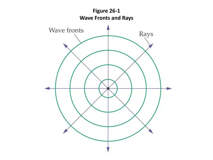
Figure 26-1 Wave Fronts and Rays. Figure 26-2 Spherical and Planar Wave Fronts. Figure 26-3 Reflection from a Smooth Surface. Reflection. Law of reflection q i = q r. Figure 26-4 Reflection from Smooth and Rough Surfaces. Figure 26-6 Locating a Mirror Image. Figure 26-8 Spherical Mirrors.

E N D
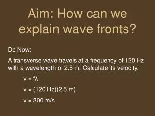
Reflection • Law of reflection qi=qr
Figure 26-14Principal Rays Used in Ray Tracing for a Concave Mirror
Figure 26-15Principal Rays Used in Ray Tracing for a Convex Mirror
Mirrors The mirror equation
Mirrors Magnification
Mirrors do =distance of the object from the mirror di =distance of the image from the mirror f= focal length of the mirror
Mirrors Distances in front of the mirror are positive. Distances behind the mirror are negative.
Table 26-1Imaging Characteristics of Convex and Concave Spherical Mirrors
Mirrors Mirror problems: 19, and 21-24 on page 883. Ray tracing worksheet.
Refraction When light transitions between two media with different indices of refraction, it will change direction if it transitions at an angle to the demarcation between the two media.
Refraction Angles of incidence and angles of refraction are measured in reference to a line normal (perpendicular) to the line of demarcation between media.
The index of refraction (n) for a medium is defined as the speed of light in vacuum (c) divided by the speed of light in the medium(v).
Refraction There is a mathematical relationship that is used to calculate the amount of bending called Snell’s Law.
Refraction If a ray is transitioning from a medium of lesser n to a medium of greater n it will bend toward the normal.
Refraction If a ray is transitioning from a medium of greater n to a medium of lesser n it will bend away from the normal.
Refraction Problems 37-42 on page 883.
Lenses Refractive properties of materials are useful in manipulating light for imaging purposes through the use of lenses.
Lenses Lenses consist of two main types converging and diverging.
Figure 26-32The Three Principal Rays Used for Ray Tracing with Convex Lenses
Figure 26-33The Three Principal Rays Used for Ray Tracing with Concave Lenses
Lenses The lens equation
Lenses Magnification
Lenses do =distance of the object from the lens di =distance of the image from the lens f= focal length of the lens
Lenses Focal length f is positive for converging(convex) lenses f is negative for diverging (concave) lenses Magnification m is positive for upright images (same orientation as the object) m is negative for inverted images (opposite orientation of object)
Lenses Image distance diis positive for real images (on the opposite side of the lens from the object) diis negative for virtual images (on the same side of the lens from the object) Magnification m is positive for upright images (same orientation as the object) m is negative for inverted images (opposite orientation of object)
Lenses do is positive for real objects (from which light diverges) do is negative for virtual objects (toward which light converges)
Lenses Problems 63-67 on page 885. Ray tracing worksheet.
Dispersion of light The index of refraction in a substance is different for light of different frequencies.
Dispersion of light The greater the frequency, the greater the index of refraction.
Dispersion of light Violet light will bend more than red light or green light, and therefore a separation of colors occurs.