Download
1 / 57
650 likes | 899 Views
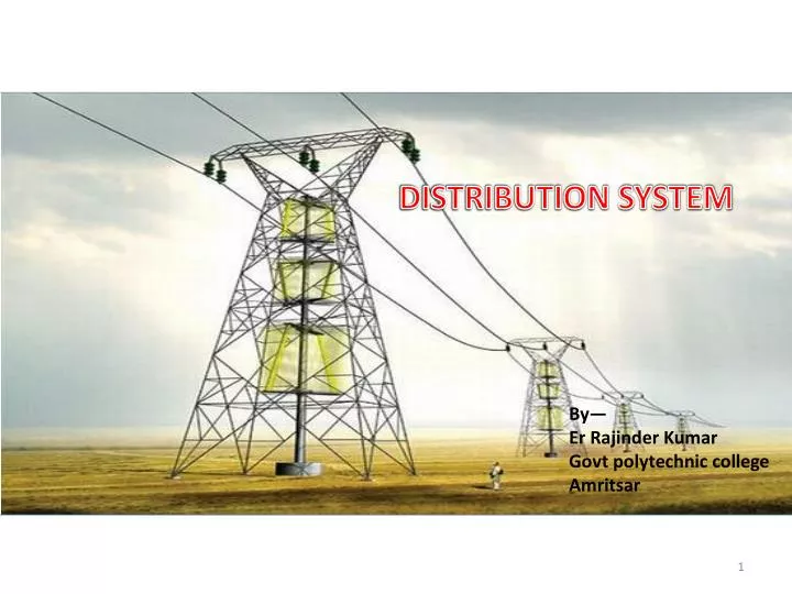
DISTRIBUTION SYSTEM. By— Er Rajinder Kumar Govt polytechnic college Amritsar.

E N D
DISTRIBUTION SYSTEM By— Er Rajinder Kumar Govt polytechnic college Amritsar
Hello viewers ,in this lecture we shall learn about the distribution system. So that dc as well as ac distribution system also we shall discuss about The components of a pole mounted substation and components fitted on lattice steel tower for transmission of a HT line. some insulators will also be discussed…..
The Transmission system can be divided into two parts:---- Primary Transmission Secondary Transmission The Distribution system can be divided into two parts:---- Primary Distribution Secondary Distribution
A distributor is set to the legal requirement that power must be supplied at a voltage within ± 6% of the declared voltage., whereas a transmission system is not subject to any such restriction . Its voltage can vary as much as 10% to 15% due to variation in loads. any restriction in transmission system is technical and not legal. The transmission system of an area is called GRID.
The different grids are inter connected through the lines to form a regional grid and the different regional grids are further interconnected to form a national grid. Each grid operates independently. However power can be transmitted from one grid to another. The maximum generation voltage in advanced countries is 33 kV while that in India is 11 kV. The amount of power that has to be transmitted through transmission lines is
The amount of power that has to be transmitted through transmission lines is very large and if this power is transmitted at 11kV the line current and power loss will be large. There fore the voltage is stepped to a higher level by using step-up transformers located in sub-stations. Also volume of conductor used in transmission lines depends upon the voltage and current.
The three phase transmission and distribution system may consist of Overhead lines Underground cables The main advantage of underground system are that it is less prone to electric hazards like rain , wind & lightning. and that it does not interfere with other amenities.
FEEDERS • These are the cables supplying power in bulk to a selected number of points called feeding points The feeders run along streets overhead (or underground, in some cases) and power the distribution transformers at or near the customer premises.
DISTRIBUTORS • Distributors are used for current Tapping for the various consumers these cables are generally having the main street for there route .
SERVICE MAIN • Service mains are the small cables teed of off from the distributors and taken into the premises of the various consumers these are low tension cables.
EFFECT OF SUPPLY VOLTAGE ON THE SIZE OF DISTRIBUTOR The allowable current density for given type of cable laid is not constant but decreases somewhat as the cable size increases. If voltage of the system is increased N folds then for a given power delivered The current is reduced to 1/Nth. Size of cable is reduced to 1/Nth.
BALANCERS The generators supplying a three-wire feeder are all connected in parallel across the outers, and it is therefore necessary to fix the potential of the middle wire midway between that of the outers, otherwise voltages will not be equal, unless the currents taken from the outers are equal.
POLE-MOUNTEDSUBSTATION The substation consisting of a transformer and other apparatus installed on the pole structure is known as pole mounted substation As the name implies such substation are installed on H-pole structure many times
COMPONENTS OF 11kV/ 400V POLE MOUNTED SUB-STATION It is an out-door type substation and is erected on a pole structure. this erected pole is also called H-pole structure The various components of such a sub-station numbered as under:-
1)---R.C.C. Pole Structure 2)--Platform for transformer 3)--Transformer 4)--Pin-Type insulator 5)-Jumpers 6)--Strain insulator 7)--Fuses 8)--Gang Operating switch 9)--P.G. Clamps
10)-Earthing 11)--Caution Plates 12)--Stay wire 13)-Anchor road 14)-Stay insulators 15)-Anti-climbing devices 16)-G.I. Pipe and bends 17)-V.I.R. Cable 18)-T.P.I.C. Switch
2nos 40x6 mm,M.S flat with nut & bolt. H.T grade, , porcelain body, glazed 2nos
Dimensions of Danger PlateTwo sizes of Danger Notice Plates as follows are recommended: For display at 415 V installations – 200x150mm--- For display at 11 KV (or higher voltages) installations – 250x200mm The corners of the plate shall be rounded off. The location of fixing holes is provisional and can be modified to suit the requirements of the purchaser.
Lettering of Danger PlateAll letterings shall be centrally spaced. The dimensions of the letters, figures and their respective position shall be as shown in figs on next slide The size of letters in the words in each language and spacing between them shall be so chosen that these are uniformly written in the space earmarked for them.
Languages of Danger PlateUnder Rule No. 35 of Indian Electricity Rules, 1956, the owner of every medium, high and extra high voltage installation is required to affix permanently in a conspicuous position a danger notice in Hindi or English and, in addition, in the local language, with the sign of skull and bones. The type and size of lettering to be done in Hindi is indicated in the specimen danger notice plates shown in Fig. 2 and those in English are shown in Figs.
Now let us discuss about the components Regarding the lattice steel tower for distribution the ac voltage. The main supporting unit of overhead transmission line is transmission tower. Transmission towers have to carry the heavy transmission conductor at a sufficient safe height from ground. In addition to that all towers have to sustain all kinds of natural calamities
So transmission tower designing is an important engineering job where all three basic engineering concepts, civil, mechanical and electrical engineering concepts are equally applicable. • Main parts of a transmission tower A power transmission tower consists of the following parts,
1) Peak of transmission tower2) Cross Arm of transmission tower3) Boom of transmission tower4) Cage of transmission tower5) Transmission Tower Body6) Leg of transmission tower7) Stub/Anchor Bolt and Base plate assembly of transmission tower
Peak of transmission tower • The portion above the top cross arm is called peak of transmission tower. Generally earth shield wire connected to the tip of this peak. • Cross Arm of transmission tower • Cross arms of transmission tower hold the transmission conductor. The dimension of cross arm depends on the level oftransmission voltage, configuration and minimum forming angle for stress distribution.
Cage of transmission tower • The portion between tower body and peak is known as cage of transmission tower. This portion of the tower holds the cross arms. • Transmission tower body • The portion from bottom cross arms up to the ground level is called transmission tower body. This portion of the tower plays a vital role for maintaining required ground clearance of the bottom conductor of the transmission line.
The “Stockbridge” type vibration damper is commonly used to control vibration of overhead conductors and OPGW. The vibration damper has a length of steel messenger cable. Two metallic weights are attached to the ends of the messenger cable. The centre clamp, which is attached to the messenger cable, is used to install the vibration damper onto the overhead conductor.
Ring Distributor A ring distributor is a distributor which is arranged to form a closed circuit and which is fed atone or more than one points. For the purpose of calculating voltage distribution, it can be looked uponas consisting of a series of open distributors fed at both ends. By using a ring distributor fed properly, great economy in copper can be
affected. If the ring distributor is fed at one point then, for the purposes of calculation, it is equivalent to a straight distributor fed at both ends with equal voltages There are 3 type of power distribution namely loop,network and radial.Radial distribution is the type of power distribution where the power is delivered from the main branch to sub-branches then it split out from the sub-branches again. it is the cheapest but least reliable network configuration.
Ring main system - In this system, various power stations or sub-stations are interconnected alternate routes, thus forming a closed ring. In case of damage to any section of the ring, that section may be disconnected for repairs and power will be supplied from both ends of the ring. A radial system has a single simultaneous path of power . The distribution systems are typically radial because networked systems are more expensive.
ADVANTAGES OF OUT-DOOR SUBSTATIONS • Fault location is easier. • Extension of the installation is easier. • Less time is required foe their erection. • The cost of civil engine4ering work is less. • Practically no danger of a fault which appears at one point being carried over to another point.
Now let us discuss some insulators used In distribution systems Pin type insulators Post type insulators Disc type insulators D-Shakle type insulators Egg type insulators Reel insulators ………etc
Pin Insulator is earliest developed overhead insulator, but still popularly used in power network up to 33KV system. Pin type insulator can be one part, two parts or three parts type, depending upon application voltage. In 11KV system we generally use one part type insulator where whole pin insulator is one piece of properly shaped porcelain or glass. As the leakage path of insulator is through its surface
In higher voltage like 33KV and 66KV manufacturing of one part porcelain pin insulator becomes difficult. Because in higher voltage, the thickness of the insulator become more and a quite thick single piece porcelain insulator can not manufactured practically. In this case we use multiple part pin insulator, where a number of properly designed porcelain shells are fixed together by Portland cement to form one complete insulator unit. For 33KV tow parts and for 66KV three parts pin insulator are generally used.
Post Insulator-- Post insulator is more or less similar to Pin insulator but former is suitable for higher voltage application. Post insulator has higher numbers of petticoats and has greater height. This type of insulator can be mounted on supporting structure horizontally as well as vertically. The insulator is made of one piece of porcelain but has fixing clamp arrangement are in both top and bottom end.
In higher voltage, beyond 33KV, it becomes uneconomical to use pin insulator because size, weight of the insulator become more. Handling and replacing bigger size single unit insulator are quite difficult task. For overcoming these difficulties, suspension insulator was developed.