Download
1 / 1
10 likes | 94 Views
Board A. #include <m8c.h> #include "PSoCAPI.h" void main() { int numPixels, i; numPixels = 0; LCD_1_Start(); M8C_EnableGInt; CSD_1_Start(); LCD_1_Position(0, 0); LCD_1_PrCString("Freq. Level:H->L"); CSD_1_InitializeBaselines();

E N D
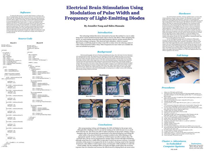
Board A #include <m8c.h> #include "PSoCAPI.h" void main() { int numPixels, i; numPixels = 0; LCD_1_Start(); M8C_EnableGInt; CSD_1_Start(); LCD_1_Position(0, 0); LCD_1_PrCString("Freq. Level:H->L"); CSD_1_InitializeBaselines(); CSD_1_SetDefaultFingerThresholds(); LCD_1_InitBG(0); while(1) { CSD_1_ScanAllSensors(); CSD_1_UpdateAllBaselines(); //detect if any sensor is pressed if(CSD_1_bIsAnySensorActive()) { if(CSD_1_bIsSensorActive(0) && CSD_1_bIsSensorActive(1)) { numPixels = 0; PRT0DR = 0x01; } else if(CSD_1_bIsSensorActive(2)) { numPixels = 10; PRT2DR = 0x01; } else if(CSD_1_bIsSensorActive(3)) { numPixels = 20; PRT2DR = 0x02; } else if(CSD_1_bIsSensorActive(4)) { numPixels = 30; PRT2DR = 0x04; } else if(CSD_1_bIsSensorActive(5)) { numPixels = 40; PRT2DR = 0x08; } else if(CSD_1_bIsSensorActive(6)) { numPixels = 50; PRT2DR = 0x10; } else if(CSD_1_bIsSensorActive(7)) { numPixels = 60; PRT2DR = 0x20; } else if(CSD_1_bIsSensorActive(8)) { numPixels = 70; PRT2DR = 0x40; } else if(CSD_1_bIsSensorActive(9)) { numPixels = 80; PRT2DR = 0x80; } else { numPixels = 0; PRT0DR = 0x01; } LCD_1_DrawBG(1, 0, 16, numPixels); } //end big if } //while } //end main Settings Board B #include <m8c.h> #include "PSoCAPI.h" unsigned char capsense; int i; void main() { M8C_EnableGInt; LCD_1_Start(); LCD_1_Init(); LCD_1_Position(0,0); LCD_1_PrCString(" The Electropam "); PWM16_1_Start(); while(1) { capsense = PRT1DR; if(capsense) { if(capsense&0x01) { //beta(14) PWM16_1_WritePeriod(38781); PWM16_1_WritePulseWidth(12927); PWM16_1_Start(); LCD_1_Position(1,0); LCD_1_PrCString("Beta-Alertness "); } else if(capsense&0x02) { //alpha(9.5) PWM16_1_WritePeriod(26316); PWM16_1_WritePulseWidth(8772); PWM16_1_Start(); LCD_1_Position(1,0); LCD_1_PrCString("Alpha-Calmness "); } else if(capsense&0x04) { //theta(4.5) PWM16_1_WritePeriod(12466); PWM16_1_WritePulseWidth(4155); PWM16_1_Start(); LCD_1_Position(1,0); LCD_1_PrCString("Theta-Drowsiness"); } else if(capsense&0x08) { //delta(2.5) PWM16_1_WritePeriod(6925); PWM16_1_WritePulseWidth(2308); PWM16_1_Start(); LCD_1_Position(1,0); LCD_1_PrCString("Delta-Deep Sleep"); } } //end outer if } //end while } //end main Beta-Alertness Alpha-Calmness Delta-Deep Sleep Theta-Drowsiness Electrical Brain Stimulation Using Modulation of Pulse Width and Frequency of Light-Emitting Diodes • Software • To design the Electropam, we used the PSoC Designer 5 software and chip-level programming. Our main code was written in C, as shown below in the source code. We used multiple if-else statements to determine which frequency and pulse width to apply to each setting. To control which mode the Electropam is on, we programmed the cap-sense slider on board A to send information to board B by storing the data in port 2 pins 0, 1, 2, and 3 and sending it to the respective pins of port 1 on board B. In the same board A code each if statement draws four bars per setting. In each if statement, we checked a separate pin using bitwise operations. The mask for the pin corresponding to the last sensor that was touched evaluates true. The control then passes to the body of the if statement where the frequency and pulse width are determined and set. To make the LEDs blink at a speed slow enough to be visible, we set the pulse width to a third of the period. The LCD is programmed to display which frequency is currently selected. Hardware Our electrical brain stimulator, which we call Electropam, is a device that induces alertness, calmness, sleep, or dreams. The Electropam is a pair of safety goggles fitted with six light-emitting diodes connected to two programmable-system-on-a-chip (PSoC) CY3214 circuit boards. Each eye of the goggles has two red light-emitting diodes (LEDs) and one green LED affixed to the lens in a triangular pattern. The LEDs are connected to the breadboard of one circuit board using extended wires. That circuit board (B) is then directly connected to the second board (A) through wires linking the ports. The reason we chose to separate the boards is because the user modules (capacitive sensor, or cap-sense, and pulse width modulators, or PWMs) did not fit on the same chip when programming. Board A allows the user to select which state is currently on using the cap-sense slider, where every two sensors is one choice and four bars are drawn on board A’s liquid crystal display (LCD) for each state and the selected setting shown on board B’s LCD. Board B uses pulse width modulation to control the blinking of the attached LEDs. When a person then puts on the goggles for, on average, twenty minutes in the absence of noise, he or she will experience a calming sensation that varys based on which option has been selected. For the individual parts of the circuit, the main focus of this project includes the cap-sense slider and PWM. The cap-sense slider is made of a layer containing an electrical charge whose sensitivity is changeable. It detects a touch when a user’s finger approaches the sensors, transferring some of the electrical charge to the user and disrupting the electrical field. Because the input to the cap-sense must remove some electrical charge in order to be detected, objects such as styluses do not work on it, making a finger the most logical and accessible input choice. The PWM controls the frequency by changing the period and high time, which is the length of time the modulator is on. The actual implementation of the PWM is explained in the software. By Jennifer Fang and Sidra Hussain • Introduction • The technology behind this device interested us because this method is a way to safely bring about certain beneficial mental states with no known side effects. When designing this device, we used existing researched and tested frequency data for certain mental states to pick which settings to program. This electrical brain stimulator, which we named Electropam, would help people in today’s tense life to reduce stress by inducing a state of calm or help insomniacs induce sleep. Other frequencies for more states are available but were not included our project. Source Code • Background • Electroencephalography, the basis of the brain stimulating technology, allows the brain's electrical vibrations to be measured and recorded. The frequencies of the vibrations for this project, ranging from about 0.5 to 30 Hz, have been classified into four states. Each state correlates with a different state of mind, and exposing the brain to these frequencies induces the brain into these states to bring about certain mental effects. The four states we use are delta, theta, alpha, and beta. Delta, which ranges from 0.5 to 4 Hz, is the dominant frequency during deep sleep. Therefore, research shows that being exposed to delta frequencies causes dream-like hallucinations. It also brings a feeling of calmness that can replace a few hours of sleep. Theta, which ranges from 4 to 8 Hz, is dominant during the first stages of sleep. This setting causes drowsiness or deep relaxation similar to meditation and is said to allow people to achieve the effects of Zen meditation in a matter of minutes rather than years. Alpha, which ranges from 8 to 14 Hz, relaxes and calms the user. Finally, beta, which ranges from 14 to 30 Hz, is dominant when a person is alert. Exposing the brain to one of these frequencies in the form of blinking lights or buzzing noises is a milder version of this technology than directly running a current to the brain. Full Setup • Procedures • Obtain two CY8C2489-24LFXI boards. • First board: open a new chip-level project in the programmable-system-on-a-chip (PSoC) Designer 5 for the CY8C2489-24LFXI. Select “C” as the language to generate main. • Place a CSD in the project. Complete the CSD wizard depending on number of sliders and sensors to use. • Place an LCD module in the project. Assign the LCD to port 4. • Generate the library files. • In the pin layout, set the output drive for port 2, pins 0, 1, 2, and 3 to “pull down.” • Use if statements to determine which sensor is been touched. Change the value of a pin in port 2 depending on which sensor is touched. See source code. • Use a bar graph to track the options for frequencies of the blinking (beta, alpha, theta, delta, in that order by frequency high to low). • Compile, build, test, debug, and repeat. • Program the first board (either of the two work). • Wire port 0_5 to port 1_5. • Second board: open a new chip-level project in PSoC Designer 5 for the CY8C2489-24LFXI. Select “C” as the language to generate main. • Place two 16-bit pulse width modulators (PWM16) into the project. • Assign values in the PWM properties and schematic. • Place an LCD in the project. Assign it to port four. • Assign the output drive of port 2 pins 0, 1, 2, and 3 to “pull down.” • Generate library files. • Initialize variables and the LCD. • Read the value from port 2. • Use if statements do determine which state to set PWM to. See source code. • Set period and pulse width values for each state. Pulse widths should be a third of the period. See source code. • Set LCD position. Print state name and description on LCD. • Compile, build, test, debug, and repeat. • Connect port 2 pins 0, 1, 2, and 3 to each other on each board to each other. • Attach LEDs to goggles. Connect to output on board using wires. • Power the boards. Test device overall. Conclusions After programming, testing, and debugging, the LEDs all blinked at the proper rates, although delta’s blinking is hard to see just by looking at the LEDs because it is so much faster than the rest. The device was able to induce relaxation on the proper settings. Using a changing value for the period that is proportional to the desired frequency and setting the pulse width to the period divided by a constant resulted in the LEDs blinking at the appropriate speeds. In tests, extended use of Electropam was able to induce sleep. We conclude that a device can be programmed to change states of mind with light stimulation, although actual time for a visible effect to take place varied from person to person. A possible extension of the project is to program the device to produce a buzzing sound at the required frequencies. This addition would require using a second pulse width modulator to make the sound audible, but the combined effect of sounds and lights would reduce the necessary exposure time for relaxation and increase the effectiveness by helping block out excess noise. Cluster 1: Adventures in Embedded Computer Systems July 2008 Instructors Rajesh Gupta, Choon Kim, Shirley Miranda, Bridget Benson, and Arash Arfaee