Download

1 / 9
130 likes | 1.18k Views
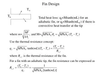
Fin Design. T . T b. Total heat loss: q f =Mtanh(mL) for an adiabatic fin, or q f =Mtanh(mL C ) if there is convective heat transfer at the tip. Fin Effectiveness.

E N D
Fin Design T Tb Total heat loss: qf=Mtanh(mL) for an adiabatic fin, or qf=Mtanh(mLC) if there is convective heat transfer at the tip
Fin Effectiveness How effective a fin can enhance heat transfer is characterized by the fin effectiveness f: Ratio of fin heat transfer and the heat transfer without the fin. For an adiabatic fin:
Fin Effectiveness (cont.) • To increase f, the fin’s material should have higher thermal conductivity, k. • It seems to be counterintuitive that the lower convection coefficient, h, the higher f. But it is not because if h is very high, it is not necessary to enhance heat transfer by adding heat fins. Therefore, heat fins are more effective if h is low. Observation: If fins are to be used on surfaces separating gas and liquid. Fins are usually placed on the gas side. (Why?) • P/AC should be as high as possible. Use a square fin with a dimension of W by W as an example: P=4W, AC=W2, P/AC=(4/W). The smaller W, the higher the P/AC, and the higher f. • Conclusion: It is preferred to use thin and closely spaced (to increase the total number) fins.
Fin Efficiency For infinite k T(x)=Tb, the heattransfer is maximum T(x)<Tb for heat transfer to take place Tb x x Total fin heat transfer qf Ideal heat transfer qmax Real situation Ideal situation
Fin Efficiency (cont.) Use an adiabatic rectangular fin as an example: Figures 8-59, 8-60
Overall Fin Efficiency Overall fin efficiency for an array of fins: qf Define terms: Ab: base area exposed to coolant Af: surface area of a single fin At: total area including base area and total finned surface, At=Ab+NAf N: total number of fins qb
Heat Transfer from a Fin Array =Ab+NAb,f
Thermal Resistance Concept L1 A=Ab+NAb,f t Rb=t/(kbA) T1 T T1 Tb T2 T R1=L1/(k1A) Tb T2