Download
1 / 15
150 likes | 240 Views
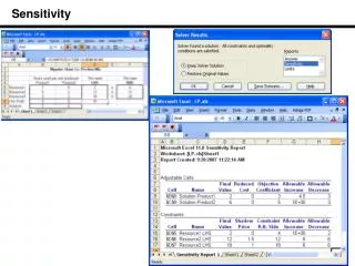
This detailed report covers statistical and systematic errors, energy analysis, beam angles, FOM calculations, systematic errors due to misalignments, cancellation mechanisms, misalignment effects cancellation, and estimation of systematic error. Key points include sensitivity analysis and error determination for p0 fwd/bwd analysis.

E N D
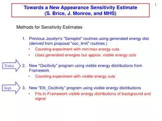
Sep. 1, 2007 JPARC TREK Collaboration meeting at Saskatchewan Updated sensitivity estimate • Statistical error • Systematic error Suguru ShimizuOsaka University
Analyzing power and FOM 0.96 0.92 e+ energy (MeV) • FOM∝AT√ N was calculated by this formula(see FIFC and PAC reports). • Analyzing power is α=0.38 (at FOM max.) • e+ energy measurement is not so important. Just accept high energy e+ component. • Best e+ angle threshold is about 0.4 e+ energy (MeV) cosθ cosθ y e+ θ e+ energy (MeV) cosθ beam e+ angle cut is effective to improve FOM, while e+ energy measurement is less important.
π0 θ Beam axis FOM for p0 angle threshold for the p0 fwd/bwd analysis FOM was determined as a function of cos θπ (see FIFC and PAC reports). <cos θT >=0.68 (at FOM max.) cosθπ cosθπ Summary of FOM studyparameters: e+ energy, e+ angle, p0 angleAT α<cosqT>a =0.38<cosqT>=0.68 ΔPT=1.2x10⁻⁴ is obtained with 2.4GKm3events under the best FOM condition (only pi0 fwd/bwd analysis). PT=
Systematic error from B field rotation Side View End View B PNfwd spectrometer PNfwd Left Right m+ 1mrad. uncertainty of B field D PT = 10-3 Left Right B PTbwd PNbwd PTfwd PNbwd p0 fwd p0 bwd π0 fwd 1+a PT bwd 1-a PT π0 fwd 1+b PN bwd 1-b PN fwd/bwd = 1+2aPT fwd/bwd = 1+2bPN ≠1 systematic error Calibration of the polarimeter misalignment using experimental data is very important.
Systematic error due to misalignments Rot(dr) misalignment Rot(dz) misalignment beam beam ideal B ideal B Asymmetry Asymmetry R comp. R comp. offset Z comp. Z comp. offset Offset is generated from Z component of muon spin Offset is generated from R component of muon spin
Systematic error due to misalignments Rot(dr) misalignment Rot(dz) misalignment beam beam ideal B ideal B Introduction of q0(See E06 technical noteNo.2)Time integrated e+ left/right asymmetry - dz sinq0 + dr cosq0 Asymmetry Asymmetry R comp. R comp. offset Z comp. Z comp. offset Offset is generated from Z component of muon spin Offset is generated from R component of muon spin
Time integrated asymmetry Km3 Black: π0fwd Red : π0 bwd q0 : the muon spin phase at t=0 In general, e+ left/right asymmetry can be described by oscillating terms and constant terms (see E06 technote No.2) q0 (deg) q0 is determined event by event. Oscillation terms can be canceled out by the time integration.
Cancellation mechanism for misalignments Characteristic θ0 dependence of PT and d. Km3 MC, PT=0, δz=5deg Km3 MC, Non-zero PT π0 bwd π0 bwd π0 fwd π0 fwd A(q0)fwd= A(q0)bwd = drcosq0-dzsinq0 A(q0)fwd≠ A(q0)bwd
Cancellation mechanism for misalignments Km3 MC, PT=0, δz=5deg Km3 MC, Non-zero PT Characteristic θ0 dependence of PT and d. Asum Asum Asub Asub Asub = 0 Asub=(Afwd−Abwd)/2. ≠ 0 Asum ≠ 0 Asum=(Afwd+Abwd)/2. = 0 d effect is drastically reduced by Asub . Effect of misalignments are cancelled out by the θ0 analysis.
Separation of PT and misalignments effect Black: no misalignment, non-zero PT Blue: δz=5deg, non-zero PT Asub Asum Asub=(Afwd−Abwd)/2. i/o i/o δ δ i/o : No misalignment δ:δz=δr= 5 deg. Asum=(Afwd+Abwd)/2. dPT (stat)= 1.3 x 10 -4 dPT (syst)< 10 -4 with 2.4G Km3 events Misalignments are now harmless!
Estimation of systematic error due to misalignments Misalignments:Assumption in MC is 5 degree Misalignments:Real case is ~mrad. If dPTsys~10-4 in real case, In case of 5 degree, dPTsys = 10-4 x 5deg. /mrad ~ 10-2 dPTsys= (2±7)x10-4 was obtained in MC should be compare The systematic error is expected to be much smaller than 10-4 .
Summary of p0 fwd/bwd analysis • Sensitivity of p0 fwd/bwd analysis: statistical error 1.2x10⁻⁴ systematic error <1.0x10⁻⁴ in total 1.2x10⁻⁴ To improve the sensitivity (1) p0 left/right analysis (2) Can we use high energy 1g detection with veto counter hit events?
PT determination for p0 left/right events • p0 left/right analysisPL component are also rotated, together with PT. • PL component can be removed by comparing p0 left and right events. Beat pattern due to the finite PT can be observed.
p0 left/right analysis • Asub=(Aleft-Aright)/2 is calculated before time integration of m decay time. • Large PL component can be removed by this subtraction. Km3 MC, Non-zero PT e+ asymmetry Black: p0 leftRed: p0 right Large PL component is seen. Asub=(Aleft-Aright)/2 PT component can be extracted.
R Z p0 left/right analysis e+ e+ detection out fwd bwd • Asub=(Aleft−Aright)/2 is fitted with,a cos(wt+f+b) a, f : fitting parameterb: 0 for e+ fwd/bwd analysisp/2 for e+ in/out analysis in black: e+ fwd/bwdred: e+ in/out Asub=(Aleft−Aright)/2. f a e+ asymmetry bwd-fwd bwd+fwd e+ asymmetry in-out in+out dPT = 1.7 x 10 -4 for 2.4G Km3 events