Download
1 / 31
380 likes | 663 Views
Large Diameter Open-End Pipe Piles for Transportation Structures. Dan Brown, PhD., P.E., D.GE. Large diameter open ended piles (LDOEPs). Driven pile Tubular steel Prestressed concrete cylinder 36 inches outside diameter or larger. Typical LDOEP Applications.

E N D
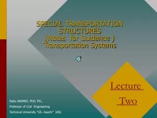
Large Diameter Open-End Pipe Pilesfor Transportation Structures Dan Brown, PhD., P.E., D.GE
Large diameter open ended piles (LDOEPs) Driven pile • Tubular steel • Prestressed concrete cylinder 36 inches outside diameter or larger
Typical LDOEP Applications High lateral load demands (often due to extreme event loading) High axial demand Deep weak soils
Typical LDOEP Applications Eliminate the need for a footing w/ single pile (pile bent) Marine construction - delivery, handling, and installation Significant unsupported length (scour, liquefaction, marine conditions)
Unique Challenges of LDOEPs Uncertainty of “plug” formation during installation Potential for installation difficulties and pile damage during driving is unlike other types of conventional bearing piles
Unique Challenges of LDOEPs Soil column within the pile may behave differently during driving or dynamic testing compared with static loading Axial resistance from internal friction Verification of nominal axial resistance is more challenging and expensive
Steel Pipe Piles Spiralweld:Continuously welded spiral from coiled sheet Rolled and welded: Plate steel rolled and welded photos courtesy Skyline Steel
Concrete Pipe Piles photo courtesy Gulf Coast Prestress Spun Cast or Bed Cast Prestressed Post-tensioned
A Simplified Examination of the Dynamic Behavior of a Soil Plug
Considerations Affecting Behavior of Steel LDOEPS Base Resistance of Steel LDOEPs on Rock and Driving Shoes • Shoe increases diameter – inside vs. outside • Shoe height and buckling of toe • Sloping rock
Considerations Affecting Behavior of Steel LDOEPS Vibratory Driving and Splicing Effect of Pile Length on Behavior and Axial Resistance • Reduced side resistance (remolding, friction fatigue, etc.) • Elastic compression enduring driving Time-Dependency of Axial Resistance
Considerations Affecting Behavior of Steel LDOEPS Driving Resistance and Dynamic Load Testing • Modeling inertial resistance of the soil plug/column • Inserts to promote plugging • Residual stresses • Limitations of hammer mobilizing resistance • Detection and avoidance of pile damage during installation
Considerations Affecting Behavior of Concrete LDOEPS Pile volume and prestressed concrete LDOEPs • Area ratio vs. steel piles – frictional resistance • Potential for plugging • Soil “bulking” in void • Hoop stress / water hammer
Considerations Affecting Behavior of Concrete LDOEPS Base resistance of concrete LDOEPs • Plugging vs mobilizing cross-section Driving Resistance and Dynamic Load Testing • Management of driving stresses • Splices rare
Design for Axial Loading Nominal axial resistance determined from driving resistance Static computations serve as guide for estimating length
Design for Axial Loading Axial Resistance in Clay Soils (“alpha”) Axial Resistance in Sands (“beta”) Methods Utilizing CPT Data (API RP2 GEO 2011) Methods Specific to Prestressed Concrete LDOEPs (FDOT)
Design for Axial Loading API RP2 GEO 2011 • Current state of practice for design for offshore industry • Long history of use • Slight differences from FHWA “alpha” and “beta” based on offshore experience • Several CPT-based methods • ICP-05, UWA-05, NGI05, Fugro05
Resistance Factor Selection Current (2013) AASHTO guidelines do not specifically represent LDOEPs. Based largely on NCHRP Report 507 (Paikowsky (2004)) • A very small number of open ended pipe piles. • LDOEPs are not documented separately from smaller piles
Design for Lateral Loading and Serviceability Not different than for other deep foundations Consider contribution to lateral stiffness of concrete plug at top of pile (connection) Consider soil plug/column contribution to axial stiffness
Summary of Current State DOT Practices Static Analysis Methods • FHWA most common, a few use API • Nordlund (sands), alpha (clays) most common Resistance Factors • AASHTO recommended most common • Few states developed their own
Summary of Current State DOT Practices Driving Criteria and Testing • Majority use wave equation analysis and/or high strain dynamic testing • Static, Rapid, and Dynamic load tests very common • Concerns with analysis of high strain dynamic data, particularly with treatment of soil plug/column
Case Histories Hastings Bridge, Minnesota St. George Island Bridge, Florida Offshore
Case Histories – Hastings Bridge, MN Key issues: Increased reliability through demonstrated pile resistance Vibrations on existing structures
Case Histories – Hastings Bridge, MN Key issues: Limitations of dynamic tests to demonstrate fully mobilized pile resistance for piles driven to refusal on rock Use of lateral load test for design
Case Histories – Hastings Bridge, MN 42-in open-end pipe piles • tw = 1 inch (for impact loads) or 7/8-in • Driven to bear on rock Axial Statnamic tests • 4,600 kips (1 in); 4,200 kips (7/8 in) • Maximum deflection about 2-½ inches; permanent sets of around ¼ in. Dynamic tests • 3,000 to 3,500 kips (Maximum hammer could mobilize)
Case Histories – Hastings Bridge, MN Statnamic tests used as basis of design Dynamic tests utilized on production piles to demonstrate: • that the piles were driven to a good seating on rock • that the piles were not damaged • that the hammer was performing as intended.
Case Histories – St. George Island, FL Key issues: Assess nominal resistance of underlying Florida limestone Determining pile order lengths to meet schedule Comparison of axial load testing methods Control of longitudinal cracking
Case Histories – St. George Island, FL Testing Program: 4 static load tests 6 Statnamic load tests 50 dynamic tests on production piles
Case Histories – St. George Island, FL Summary of test results for St. George Island Bridge (Kemp and Muchard, 2007) Reasonable agreement between static and Statnamic Dynamic tests slightly under-predict vs. static
Case Histories – St. George Island, FL Longitudinal cracks were observed in 7% of piles, usually within three to four weeks after driving Determined to be “water hammer” from build-up of fluid soil inside the pile annulus Excess “hoop stresses” resulted in cracking Contractor elected to monitor and clean out plug/soil column - no further cracking
Conclusions More LDOEP for transportation structures Advantages, limitations identified Some different engineering concepts required Questions?