Download
1 / 16
160 likes | 290 Views
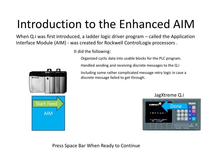
When Q.i was first introduced, a ladder logic driver program – called the Application Interface Module (AIM) - was created for Rockwell ControlLogix processors. It did the following :. Introduction to the Enhanced AIM. Organized cyclic data into usable blocks for the PLC program.

E N D
When Q.i was first introduced, a ladder logic driver program – called the Application Interface Module (AIM) - was created for Rockwell ControlLogix processors . It did the following: Introduction to the Enhanced AIM Organized cyclic data into usable blocks for the PLC program. Handled sending and receiving discrete messages to the Q.i Including some rather complicated message retry logic in case a discrete message failed to get through. JagXtreme Q.i AIM Retry Feed Start Feed Start Feed Done Done Cyclic Data Cyclic Data Press Space Bar When Ready to Continue
Enter the IND780 When the IND780 Q.i was introduced, Mettler-Toledo made sure that it was compatible with the original "Classic" AIM. Including how the messaging worked. IND780 Q.i AIM Start Feed Start Feed Done Cyclic Data Cyclic Data But we also saw an opportunity for some improvements! Press Space Bar When Ready to Continue
Simplify with Cyclic Data If a "little burp" occurs and a cyclic message gets lost, it's not usually a problem because another cyclic message will be along shortly. No complicated retry logic is necessary! IND780 Q.i AIM Cyclic Data Cyclic Data Cyclic Data That's the basic idea behind the Enhanced AIM. Press Space Bar When Ready to Continue
Field Bus Bridge Comparison Merging the Discrete Messages in with the Cyclic Data caused the cyclic data slots to expand – which changed the number of Instruments that will fit on one Field Bus Bridge card. 12 Scales and Flow meters per Bridge 24 Scales and Flow meters per Bridge Classic AIM Enhanced AIM 20 Bytes for each Instrument 36 Bytes for each Instrument Note the I/O Assembly Instance Sizes Note the I/O Assembly Instance Sizes 496 Bytes total 432 Bytes total Press Space Bar When Ready to Continue
Enhanced AIM and new IND780 Features There are a number of new features only available using the Enhanced Communication Mode • New Feature – Bit Commands Bit Commands allow commands to the Q.i to be triggered with a single bit. Details for these new features are covered in the IND780 Q.i Technical Manual. • New Feature – Stored Commands Stored Material Feed Commands allow a sequence of feeds to be set up, and then simultaneously triggered using a single 'GO' command. New Cyclic Status values Press Space Bar When Ready to Continue
AIM Configuration Comparison There are a number of Configuration parameters that are shared between the two AIM's. For the most part, you should be able to accept the default parameters, except for the Number of Bridges. You must tell the AIM how many bridges it needs to process. This bit must be turned on when a bit command is being issued. It should be turned off any other time. Press Space Bar When Ready to Continue
Mixed Fieldbus Configurations The Classic AIM was setup by default to only allow one field bus to be used at a time. While mixing Field Busses could be done, it required a significant amount of customized programming. The Enhanced AIM moves the Field Bus designation to the Bridge configuration, which allows the user to choose what field bus to use for each Bridge. Bridge #1 Bridge #2 Bridge #3 Bridge #4 Bridge #5 Bridge #6 Bridge #7 Press Space Bar When Ready to Continue
Bridge Configuration The Bridge configuration is where we decide what Bridge Assembly slots will be assigned to which E_AIMInstrument index positions. Number of Instruments on this Bridge (enter 1 to 12) These are READ ONLY, and indicate the Index range that the Bridge covers. Number of Instruments on this Bridge (enter 1 to 12) The only things that need to be configured for the Bridge are: NumberOfInstruments – How many scales and Flowmeter will the Bridge have. ENetCommunicationsEnable – It's either Ethernet/IP or ControlNet. Press Space Bar When Ready to Continue
IND780 Q.iMPACT: AIM versus Enhanced AIM - 2 Classic AIM Enhanced AIM • Same basic Instrument structure available. • Addition of Bit Commands • Timeout Timer Added to Response Structure Identical If a Timeout occurs, puts a 100 into the Command Status Press Space Bar When Ready to Continue
IND780 Q.iMPACT: AIM versus Enhanced AIM - 3 • Cyclic Data remains the same -- with some additions. Press Space Bar When Ready to Continue
IND780 Q.iMPACT: AIM versus Enhanced AIM - 4 • Handshake structure is simplified In both AIM's, set this bit to 1 to trigger a command that you have already set up with MOV instructions into the ".Command" structure. Press Space Bar When Ready to Continue
How to Trigger a Feed Write the Material Path Write the Command Number Leave the Group and Overlap numbers set to zero (non-overlap) Write the Target Weight Write the + and - Tolerances Monitor the Command and Transfer Status words. Latch the CDReady bit (Send Command) Monitor the Feed Complete bit Press Space Bar When Ready to Continue
Sample Feed Start Logic Note how the logic is set up to execute the rung only once. A one-shot could also be used for this purpose. Press Space Bar When Ready to Continue
Sample Feed Monitoring Logic After the feed is triggered, wait a short time to allow the feed to start before monitoring its progress. Wait for the feed to be flagged as being complete Make sure that the status values are in a good range. Otherwise, process the error. Press Space Bar When Ready to Continue
Useful links Link to Sample PLC program used here Configuration Files that can be loaded into an IND780 Q.i to make it work with the sample PLC program. Recommended to use the IND780 Q.i Dashboard "Restore Cluster" command to install the files. The IP address of the unit is assumed to be 192.168.0.1. Link to IND780 Q.i Configuration for Demo.zip PC Scale Simulator. Allow a PC to simulate a running scale during a feed. You will need to install and run this program to run the Demo PLC program. Be sure to edit the configuration, and set the IP address of the IND780 unit in the simulator to match the IP address in the unit being used. Scale Simulator Install Link to Classic and Enhanced AIM Drivers and support files Link to IND780 Q.i FTP Support Site Press Space Bar When Ready to Continue