Download
1 / 21
210 likes | 376 Views
g2p/GEp Beamline. Tim Michalski Project Lead. Overview. Facilitate the design, procurement, and build of the beamline – up to the target chamber g2p/GEp Beamline Overview Experimental Plan Project Overview Project Status Project Challenges with Risk Mitigation

E N D
g2p/GEp Beamline Tim Michalski Project Lead
Overview Facilitate the design, procurement, and build of the beamline – up to the target chamber g2p/GEp Beamline Overview Experimental Plan Project Overview Project Status Project Challenges with Risk Mitigation Project Schedule and Milestones
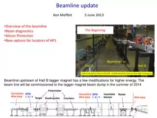
Beamline Overview A second configuration will have the target at the pivot and a longer articulating arm.
Experimental Plan Target Elevated by 9cm *** - FZ1 and FZ2 in position for 2.2 GeV run, but with half field strength on FZs and Target magnets Rev 3
Run Trajectories FZ1 Target Target FZ2 FZ1 FZ2
Beam Diagnostics Girder “Articulating Arm” – Region 3
Project Overview • Design, procurement, component calibration and testing • Now through May, 2011 • Some components arrive after May • Access to Hall A for installation • May 16, 2011 • Installation completion – start of Physics • November 19, 2011
Project Status • Regions 1 and 2 designs complete and material ordered • Region 3 design complete – procurement under way • Calorimeter controller repaired and SW upgrades complete • I&C electronics designed and being built • New Transport electronics being built for existing BPMs in Hall A • Safety systems for experiment reviewed • Resource planning integrated into 6MSD schedule
Project Challenges • BPMs and BCMs for Low Current data • Mitigation • BPM – short M15 style, new electronics, tested in North LINAC • BCM – new receiver, tested in Hall A • FZ Magnet PS requirements evolving • Need up to 4 kG, requiring 231A for FZ1 • Need up to 8 kG, requiring 465A for FZ2 • Mitigation – assessed capabilities of magnet power supplies in Hall C – meet requirements – assembling spares
Project Challenges • Acquisition of equipment from various sources • FZ magnets, corrector magnets, slow raster, new BPMs, power supplies, controllers • Mitigation – get control as soon as possible, test and calibrate early (before installation) • Resurrection of Tungsten Calorimeter • Reposition in beamline, re-establish functionality, recalibrate • Mitigation – Controller extracted from Hall A, repaired, SW complete
Project Challenges • Slow Raster control issues in previous experiment • Mitigation – New function generator – Testing in Progress by Physics Fast Electronics Group • Installation at the same time as 12 GeV upgrades during 6 month down • Mitigation – tied to detailed 6MSD planning – all resources identified in schedules – have ~3 weeks float
Project Challenges • Not all material for installation on site yet • Mitigation • FZ2 Stand procurement being managed – potential impact to 6MSD installation reviewed • Viewer and Articulating Arm Girder / Positioning – manage through Machine Shop and local vendors
Safety – PSS / FSD • Uses standard BLA system components • Monitoring FZ magnet PS current – limits set to ensure beam is controlled successfully through the chicane • FSD masking for Calorimeter Operation • Viewer in chicane – allows MCC Operators to view beam for steering confirmation • Thermocouples on LC dump • Viewer on LC dump – allows MCC Operators to view beam for steering confirmation • Update PSS sweep procedure as required after walk-through, equipment installation • “Lock Out” FZ2 stand control – remove controller