Download
1 / 65
670 likes | 1.23k Views
ATOMIC SPECTROSCOPY. Lecture 5. ATOMIC SPECTROSCOPY. Three techniques (methods) included in atomic spectroscopy: 1) atomic absorption spectroscopy 2) atomic emisssion spectroscopy 3) atomic fluorescene spectroscopy. Atomic spectroscopy.

E N D
ATOMIC SPECTROSCOPY Lecture 5
ATOMIC SPECTROSCOPY • Three techniques (methods) included in atomic spectroscopy: 1) atomic absorption spectroscopy 2) atomic emisssion spectroscopy 3) atomic fluorescene spectroscopy
Atomic spectroscopy • In order to perform atomic spectroscopy, atoms of the analyte must first be formed, usually in the form of an atomic vapor. Atomization – the process by which a sample is converted to an atomic vapor. Atomizer – a device used to converted a sample to an atomic vapor.
Atomic spectroscopy • Three types of atomizer: 1) flame atomizer 2) plasma atomizer 3) electrothermal atomizer
Atomization process • Solution of the analyte is evaporated rapidly at an elevated temperature to yield a finely divided solid. • Further heating will break down into gaseous atoms.
Process occuring during atomization Nebulization – Conversion of the liquid sample to a fine spray. Desolvation - Solid atoms are mixed with the gaseous fuel. Volatilization – Solid atoms are converted to a vapor in the flame. • There are three types of particles that exist in the flame: 1) Atoms 2) Ions 3) Molecules
1. Types of Flames Fuel / OxidantTemperature H–CC-H acetylene / air 2100 – 2400 C (most common) acetylene / N2O 2600 – 2800 C acetylene / O2 3050 – 3150 C • Selection of flame type depends on the volatilization of interest. 2. Flame Structure • Interzonal region is the hottest part of the flame and best for atomic absorption. • Oxidation of the atoms occurs in the secondary combustion zone where the atoms will form molecular oxides and are dispersed into the surroundings.
Temperature Profile Temperature profile in degrees Celsius for a natural gas-air flame
3. Burners • Two types of burners in flame spectroscopy i. Turbulent flow (total consumption burner) ii. Laminar flow (premix burner)
Turbulent Flow Burner • Nebulizer & burner are combined into a single unit. • Sample is drawn up the capillary & nebulized • Sample flow rate: 1 to 3 mL/min
Turbulent Flow Burner • Advantage: • introduce relatively large & representative sample into the flame. • Disadvantages: • A relatively short path length through flame • Problems with clogging of the tip • Burners noisy from electronic and auditory stand point
Laminar Flow Burner • Sample is nebulized by the flow of oxidant past a capillary tip. • Resulting aerosol then mixed with fuel & flows past a series of baffles that remove all but the finest droplets. • Majority of the sample collects in the bottom of mixing chamber, drained to a waste container. • Aerosol, oxidant & fuel are burned in a slotted burner that provided a flame, 5 – 10 cm in length.
Laminar Flow Burner • Advantages: i. Provide quiet flame ii. Longer path length, enhance sensitivity & reproducibility • Disadvantages: i. Lower rate of sample introduction ii. Possibility of selective evaporation of mixed solvents in the mixing chamber, create analytical uncertainties. iii. Mixing chamber contains a potentially explosive mixture that can flash back if the flow rates are too low.
Atomic Absorption Spectroscopy (based on flame) • Currently the most widely used of all the atomic methods. • Simplicity, effectiveness, relatively low cost. • Flame atomization best for reproducibility (precision)(<1%)
Atomic Absorption Spectroscopy (based on flame) • The spectra result form the atomized sample absorbing photons of radiation of the appropriate energy (wavelength). • Energy of radiation absorbed by a vaporized atom is identical with that needed to bring about excitation to a higher electronic state. • Transitions: excitation of an electron from ground state to a higher energy level E1 E0
Spectrophotometers • Contain same basic components as an instrument designed for absorption analysis of solution. • Source sample container (flame or hot surface) selector detector readout system
AA Spectrophotometer Design 1. Single Beam Instrument • The modulated power source can be replaced by a chopper
AA Spectrophotometer Design 2. Double-Beam Instrument
Double-Beam Instrument • Radiation from hollow cathode lamp is split into 2 beams • One passes through the flame • The other around the flame • A half-silvered mirror returns both beams to a single path then pass through the monochromator then detector. • Note: monochromator placed between sample and detector • Eliminates most of the radiation originating from the flame.
A. Radiation Sources for AAS LINE SOURCE – narrow emission bands. Examples of line source used in AAS: Electrodeless discharge lamp (EDL) Hollow cathode lamp (HCL)
1. Hollow Cathode Lamp (HCL) • light source in AA instrument • light from this lamp exactly light required for the analysis, even no monochromator is used. • atoms of metal tested are present within the lamp.
How does the Hollow Cathode Lamp works? • When lamp on, atoms are supplied with energy • Causes atoms elevate to excited states • Upon returning to ground state, exactly the same wavelength that are useful in the analysis are emitted • Since the analyzed metal with exactly the same energy levels that undergoes excitation • Hollow cathode lamp MUST contain the element to be determined
Mechanism of excitation process in Hollow Cathode Lamp • Lamp is a sealed glass envelope filled with argon (or Neon) gas • When lamp is ON, Ne atoms are ionized with electrons drawn to anode (+ charge electrode) • The Ne ions, Ne+ bombard the surface of the cathode (- charge electrode) • Metal atoms, M, in the cathode are elevated to the excited state and are rejected from the surface as a result of this bombardment
Mechanism of excitation process in Hollow Cathode Lamp • When atoms return to ground state, characteristic line spectrum of that atom is emitted • This light is directed at the flame, where unexcited atoms of the same element absorb the radiation and are themselves raised to the excited state • Absorbance is measured, and related to the concentration
Electrodeless Discharge Lamp (EDL) • Constructed of a metal or salt of interest sealed in a quartz tube filled with a noble gas (Ne or Ar) at low pressure (1 – 5 torr). • The noble gas is ionized and accelerated by a strong radio-frequency (RF) or microwave field and in turn excite the metal or salt of interest. • Provide radiant intensities usually one to two orders of magnitude greater than HCL.
Source of Modulation • Function: • Employed in AAS to distinguish between the component of radiation arising from the source and the component of radiation arising from the flame background • Device: light chopper
Source Modulation Light chopper • A chopper or a modulated power supply is used to modulate the source radiation that passes through the atomizer (flame). • The chopper rotates resulting in an alternating atomic absorption and atomic emission signal. • The signal from emission of radiation will be continuous and can be substracted from the modulated AA signal.
Light chopper • Eliminate the effects of radiation from the flame • Light is “chopped” with a rotating half-mirror so that detector sees alternating light intensities • One moment, only light emitted by flame is read since the light from the source is cut off • Next moment, light from both the flame emission & transmission of the source’s light is measured since the source’s light is allowed to pass • The elements of the detector is such that the emission signal is substracted from the total signal & this difference is what we measured.
Questions • In flame atomic absorption spectroscopy, briefly describe the ‘atomization’ process which the analyte undergoes. • Why is source modulation employed in atomic absorption spectroscopy? Name the device used for this purpose. • Name the common line source used in AAS.
INTERFERENCES Spectral interference Chemical interference
Spectral interference • Arise when particulate matter from atomization scatters the incident radiation from the source. • Or when absorption or emission of an interfering species either overlaps or lies so close to the analyte absorption that resolution by the monochromator becomes impossible.
Spectral interference (simple words) • Is one in which the spectral line of the elements being determined overlaps with a spectral line (or band) from another element present in the sample. • The effect of the element will also be measured & thus the results will be incorrect.
Spectral interference The most common method of solving this problem i) Tune the monochromator to a different spectral line for the element of interest so that there is no overlap. ii) secondary lines (can be found in the literature)
Chemical interefrence • 2 common types of chemical interferences (that reduce the concentration of free gaseous atoms) (i) ionization (ii) formation of molecular species
Chemical interference – Ionization • Sample (liquid/solid) must be vaporized & atomized in a high temperature source such as flame. • This high temperature environment lead to ionization of the analyte atoms. • Analyte ionization can be supressed by adding a source of electrons, which shifts the equilibrium of the analyte from the ionic to the atomic form. • Cesium and potassium are common ionization supressors that are added to analyte solutions. Analyte Analyte+ + e-
Chemical interference – Ionization • Cesium and potassium are common ionization suppressors that are added to analyte solutions • These atoms (Cs & K) are easily ionized & produce a high concentration of free electrons in the flame.
Chemical interference – Refractory Formation • Some elements can form refractory compounds that are not atomized in flames. • E.g. in the presence of phosphates, which interferes with calcium measurements due to formation of refractory calcium phosphate. • Formation of refractory compounds can be prevented or reduced by adding a releasing agent.
Chemical interference – Refractory Formation • For calcium measurement: • Adding lanthanum to the sample (and standard) solutions binds the phosphates as LaPO4. • LaPO4 has a very high formation constant, Kf and effectively ties up the phosphate interferent.
Quantitative Analysis • Calibration Curve • Standard Addition Method • Absorption behavior follows Beer’s Law & concentration of unknown are determined the same way. • All atomic species have an absorptivity, a • Pathlength, b is width of the flame • A = abc
Calibration Curve Method • A general method for determining the concentration of a substance in an unknown sample by comparing the unknown to a set of std sample of known concentration. • Plot is linear over a significant concentration range (the dynamic range). • Analysis should never be based on the measurement of a single standard with assumption that Beer’s law is being followed.
Standard Addition Method • Extensively used in AAS • Compensate for variation caused by physical & chemical interferences in the analyte solution • The most common way involves adding one or more increments of a standard solution to sample aliquots of the same size. • This process is often called spiking the sample. • Each solution is then diluted to a fixed volume before measurement.
Example: Standard Addition Method The chromium in an aqueous sample was determined by pipetting 10.0 mL of the unknown into each of five 50.0 mL volumetric flasks. Various volumes of a standard containing 12.2 ppm Cr were added to the flasks, following which the solutions were diluted to the volume. 1. Plot the data. 2. Calculate the concentration of Cr in the sample.
Standard Addition - if Beer’s law is obeyed, A = bVstdCstd + bVxCx VtVt = kVstdCstd + kVxCx k is a constant equal to b Vt
Standard Addition - Plot a graph: A vsVstd (should yield a straight line) A = mVstd + b slope; m = kCstd intercept; b = kVxCx Concentration of unknown: Cx = bCstd mVx
Detection Limits (ng/mL) Nanogram/mililiter = 10-3g/mL = 10-3ppm
Accuracy • Relative error associated with a flame absorption analysis is the order of 1% to 2% • With special precautions, this figure can be lowered to a few tenths of one percent.
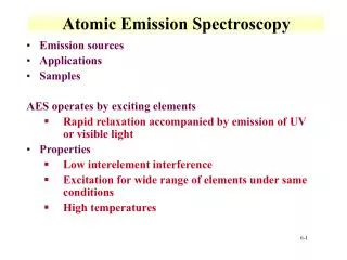
AAS and aes • Both methods use atomization of a sample and therefore determine the concentrations of elements. • For AAS, absorption of radiation of a defined wavelength is passed through a sample and the absorption of the radiation is determined. The absorption is defined by the electronic transition for a given element and is specific for a given element. The concentration is proportional to the absorbed radiation. • In AES, the element is excited. A rapid relaxation is accompanied by emission of UV or visible radiation is used to identify the element. The intensity of the emitted photon is proportional to element concentration.