Download
1 / 24
260 likes | 488 Views
A CAMERA CALIBRATION TECHNIQUE USING TARGETS OF CIRCULAR FEATURES. Ginés García Mateos Dept. de Informática y Sistemas Universidad de Murcia - España. INTRODUCTION. Camera calibration: estimation of the unknown values in a camera model. Intrinsic parameters. Extrinsic parameters.

E N D
A CAMERA CALIBRATION TECHNIQUE USING TARGETS OF CIRCULAR FEATURES Ginés García Mateos Dept. de Informática y Sistemas Universidad de Murcia - España
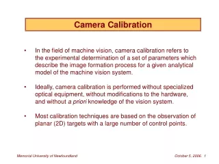
INTRODUCTION • Camera calibration: estimation of the unknown values in a camera model. • Intrinsic parameters. • Extrinsic parameters. • Calibration target: object of known geometry, easy to detect and locate, used in calibration.
INTRODUCTION • The whole procedure of camera calibration [Heikkilä et al. 97]: • Determinate a camera model. • Control point location in the images. • Camera model fitting. • Image correction for distortion. • Estimate the errors of the previous stages.
INTRODUCTION • Much research has been devoted to model fitting. • Control point location: • Design physical target structure. • Design an algorithm for target detection and location. • Goals: accuracy, robustness, efficiency, simplicity.
TARGET DESIGN • Previous work: square features. • Typical methods use: • Edge, segment, corner detection. • Line intersections. • Contour following.
TARGET DESIGN • Previous work: dot features. • Point features (less than 5 pixels radius). • Centroid calculation. • Used in photogrametry.
TARGET DESIGN • Circular features. Key ideas: • Circles (ellipses) are mapped to ellipses (using perspective projection). • Ellipses are the most simple shape to describe, detect and locate.
TARGET DESIGN • Previous work based on centroid. • Problem of perspective bias: ellipse centroid is not necessarily the projected centroid of the circle.
TARGET DETECTION/LOCATION • Process for detection and location of the target. Main steps: • Detection and location of ellipses. • Extraction of invariant points. • Matching with known points of the target. • Then model fitting (DLT) is applied.
TARGET DETECTION/LOCATION • Ellipse detection and location: • Image binarization. • Threshold: median value of partial histogram. • Connected component grouping. • Gaussian component description. • For each region: , and number of points.
ELLIPSE DETECTION/LOCATION Acquired image Binarization Connected compo-nent grouping Gaussian description
ELLIPTICAL SHAPE TEST • Gaussian parameters: , . • Ellipse mayor and minor radius: a, b • Ellipse area: SR=ab • Radius from gaussian parameters:
TARGET DETECTION/LOCATION • Ellipse location is insufficient: invariant points should be extracted. • Feature points in a target of circles. • Ellipse centroid is not an invariant feature point. • Invariant feature points can be obtained using relations between coplanar circles.
TARGET DETECTION/LOCATION • Tangent invariance: supposing perspective projection common tangent property remains invariant. Perspective projection
TARGET DETECTION/LOCATION • Some conclusions don’t held when radial distortion is considered. • Dealing with distortion: • Iterative method: parameter calculation/image correction. • Independent estimation (and correction) of distortion.
EXPERIMENTAL RESULTS • Tests are centered on the target detection/location procedure. • Accuracy: feature point location. • Robustness: defocusing and noise. • Efficiency: computation time. • Acquisition: low-cost videoconference camera QuickCam Pro (Logitech). • Computer: off-the-self PC, with K6 at 350Mhz.
EXPERIMENTAL RESULTS • Target used in the experiments. 320x240 pixels 256 gray levels • Manual measure to determine ground-truth positions.
EXPERIMENTAL RESULTS Location error vs. ellipse size in images
EXPERIMENTAL RESULTS • Manual measure is insufficient. • Accuracy of the method (using ideal images): 0.05 pixels mean, 0.03 pixels standard deviation. • The target was detected in 97% of the images.
EXPERIMENTAL RESULTS • Robustness to defocusing and noise. Location error vs gaussian smoothing Location error vs. random noise
EXPERIMENTAL RESULTS • Efficiency: • The main process is a connected component labeling algorithm. • This requires a single scanning of the image, with a constant cost per pixel. • The whole process can be made at approx. 10 Hz.
CONCLUSIONS • A technique for camera calibration is proposed based in the use of circles as target features. • This contribution is centered in target detection/location. • Process of detection and location: • Gaussian description of connected component. • Feature point calculation and matching.
CONCLUSIONS • The method is simple and low-level, which implies efficiency and robustness. • Subpixel accuracy is clearly reached. • Highrobustness to noise and defocusing. • The technique is suited for automated systems.
LAST • This work has been supported by CICYT project TIC98-0559. • Línea PARP web page: http://www.dis.um.es/parp • Muito obrigado