Download

1 / 11
110 likes | 239 Views
Estimating Mining Induced Stress. Penny Stewart BEng(Mining) PhD. Estimation of Elastic Stress. All empirical design tools, across all disciplines of engineering have one thing in common – They must be applied consistently

E N D
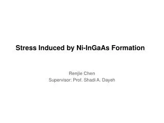
Estimating Mining Induced Stress Penny Stewart BEng(Mining) PhD
Estimation of Elastic Stress • All empirical design tools, across all disciplines of engineering have one thing in common – They must be applied consistently • Now that 3D models are commonly used, it is worth checking how this affects 2D derived mining induced stresses upon which stability charts are based. • 1980s to late 1990s, induced stresses were estimated using 2d plain-strain charts (Stewart and Forsyth, 1995)- Kirsch equation closed form linear elastic solution. • Charts not applicable for low aspect ratios in the database • Map3d boundary element • Most authors used 2d stress estimation methods Need to check Map3d against 2d model eg Phases2d
Example: South Crofty mine: Stope320 15H Map3d Stress Estimation Span = 32 m Hangingwall Width = 17m Stress Resolution Grid 3 Height = 75 m 3 -0.94 MPa
Example: Stope 320 15HPhases 2d Stress Estimation 3 -3.2 MPa 3
Estimation of Elastic Stress II • 2d Phases hybrid boundary element/finite element estimated larger tensile stresses than Map3d • Difference between Phases2d and Map3d could not be explained for stopes approaching 2d geometry • ie. Aspect ratio >5
Estimation of Elastic Stresses III • Further investigation required • South Crofty case study used to compare numerical modelling programs • High aspect ratio = 83 (strike span to width) Theoretically, 2d should be very similar to 3d model results • Compare FLAC3D (finite element) with Map3d (boundary element)
FLAC3D Stress Estimation Stope 3=-1.99 MPa 3=-7.59 MPa
Some difference between FLAC3D and FLAC Comparison of Stress Estimation Method: South Crofty
Comparison of Stress Estimation Methods @ Bottom of Stope Bottom of stope less sensitive to element size
Conclusions: Comparison of Stress Estimation Methods • FLAC3d, 2d FLAC and Map3d produce similar values Map3d stress estimates of induced stresses will be used, not Phases2d • Further investigation is required to explain why Phases2d is predicting larger tensile stresses than Map3d, FLAC3d and 2d FLAC • Comparison of codes