Download
1 / 22
220 likes | 344 Views
Lecture 15. Power. Circuits. Supplied energy (tries to accelerate electrons). Dissipated energy (slows electrons down. Energy is transformed into thermal energy, light, etc). Work by the electric field when a charge d q moves across a potential difference V :. Power supplied:.

E N D
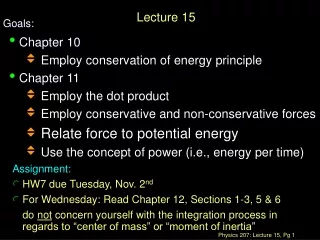
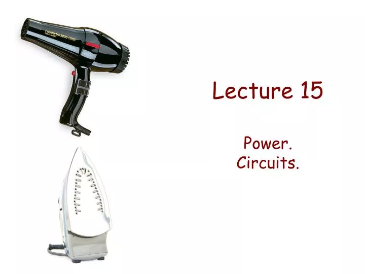
Lecture 15 Power. Circuits.
Supplied energy (tries to accelerate electrons) Dissipated energy (slows electrons down. Energy is transformed into thermal energy, light, etc) Work by the electric field when a charge dq moves across a potential difference V: Power supplied: Power dissipated (in resistor): For Ohmic resistors Power dissipation in a resistor Battery = - Supplied energy Resistor
Or for fun: DEMO: Current through a pickle Example: Resistance of a bulb Power dissipation can be bad (loss in transmission wires) or good (bulb, hair drier, etc) Example: 75-W bulb
Current takes the easiest path Short circuit Another way of burning things… If you connect the ends of a battery, the generated current is huge (the resistance of the wires is usually low). A lot of energy is released in a short time. Can even produce an explosion!
Resistor circuits = One or more batteries connected to one or more resistors, and current flowing through them. Some general rules 1. Current is conserved (because charge is conserved!) 2. Wires are ideal (no resistance) unless otherwise indicated. So two points along the same wire have the same potential, or the voltage drop across a wire is zero. 3. A battery produces a fixed increase in potential
Current (water flow) Resistors = potential drops (ramps with obstacles) Battery = fixed potential increase (water pump) Ideal wires = constant potential (flat sections) The water circuit analogy
The same current flows through both: A ● R1 I1 = I2 I R2 B ● Resistors in series Two resistors R1 and R2 are in series when they are connected one after the other:
A ● A ● R1 I I R2 B ● B ● The same current flows through the equivalent resistor: Ieq = I1 = I2 Req
V1 = VA – VC V2 = VC – VB A ● Veq = VA – VB A ● R1 R2 B ● B ● The potential difference is different for each: Veq = V1 + V2 Req C ●
Use series connection to increase resistance Note that DEMO: Adding resistors in series. Resistors in series: … R2 R3 R1 And remember that:
This is the mechanical equivalent of two resistors in series: R1 Veq R2 R1 Veq R2 Veq = V1 + V2 I1 = I2
DEMO: Cu-NiCr segments. Current vs power The current thorough resistors in series is the same. The power dissipated in each resistor and the voltage across each resistor are NOT (unless they are identical resistors) NiCr NiCr Cu NiCr Cu Cu NiCr Cu I I Resistivities: NiCr glows!
I A ● R1 R2 B ● Resistors in parallel Two resistors R1 and R2 are in parallel when they are connected to the same potential difference VA - VB. V1 = V2 (= VA – VB )
The current flowing through the circuit is the same in both cases: A ● Ieq= I1 + I2 R1 R2 Ieq I2 A ● I1 B ● Req B ● The equivalent resistor is also connected to the same potential difference: Veq= V1 = V2 (= VA – VB )
Use parallel connection to decrease resistance Note that Resistors in parallel: … R2 R3 R1 … And remember that:
Current splits I1 I3 I2 R1 In this case, R2 and R3 are in parallel to each other (and then in series with R1): Veq R2 R3 R1 R3 R2 V2 = V3 I1= I2 + I3
Example: Resistor circuit V0 What is the current through the R1? R2 R1 • 1/5 A • 1/4 A • 1/3 A • 1/2 A • 3/5 A R3 V0 = 10 V R1 = 5.0 Ω R2 = R3 = 10 Ω
V0 ( ) ) V0 = 10 V R1 = 5.0 Ω R2 = R3 = 10 Ω I1 R2 R1 I2 R3 ( I • Note that (they are frequent mistakes): • The voltage drop across each resistor is not V0 • The current is not the same for all resistors • The current is not equally split at the junction
I1 I2 V0 V0 = 10 V R1 = 5.0 Ω R2 = R3 = 10 Ω I R2 R1 R3 3 equations, 3 unknowns.
Transmission line resistance R A B Electrical plant I C is small High voltage transmission lines Pdel = power to be delivered to the costumer (fixed). The power loss in the line is If R is small and the supplied voltage VAC is large,